Hot Plate Soldering
Published on 2016-03-21 in Mechatronic Ears.
The PCBs that I wrote about last time were not the real PCBs. OSHPark has made a mistake in the board thickness (a new option that they have), and sent me the boards again, this time thinner. I didn’t realize that, so I was quite surprised to see the second shipment, but all is good.
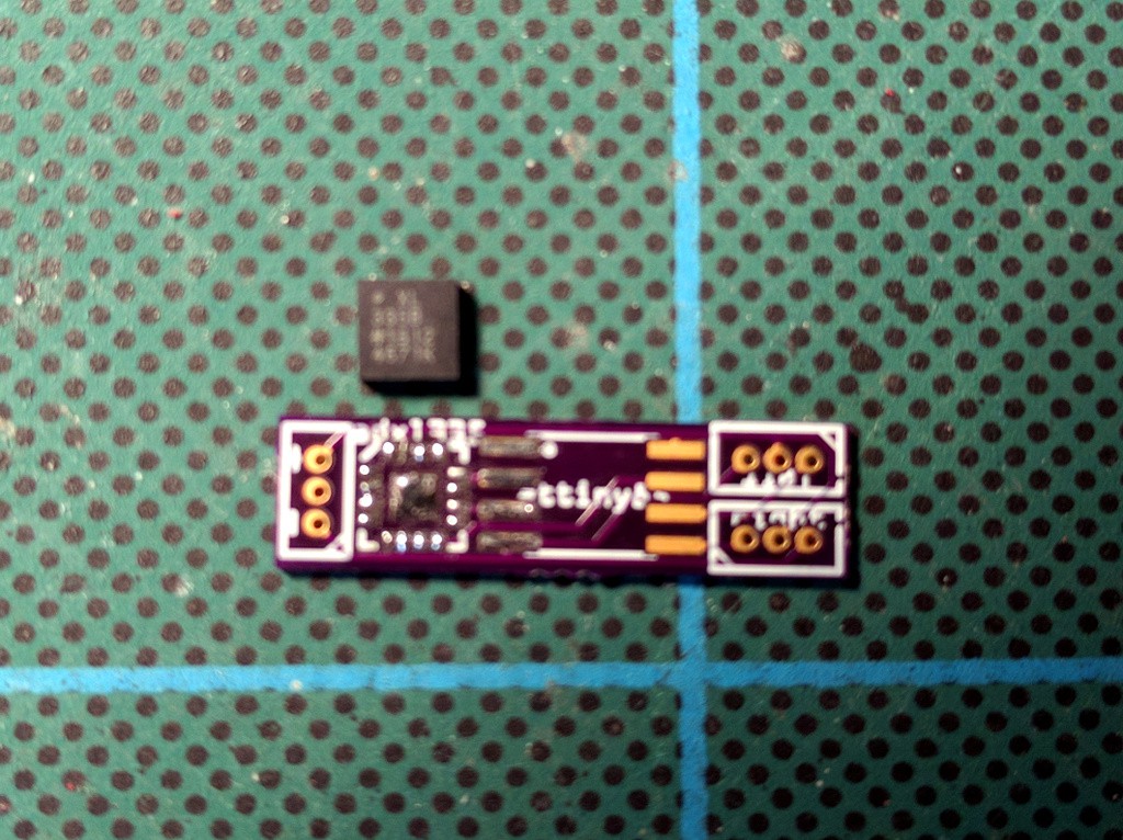
The GY-61 breakout kit also arrived, so I’m ready to try and solder it on that board. This is a “LFCSP LQ” surface-mount package, so impossible to do with a hand soldering iron. At the hackaday channel someone suggested using a kitchen stove, so I have that a try. First, I tinned the board:
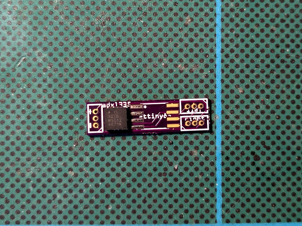
Then I covered it in flux, and went to the kitchen. I have an electric stove with a glass top, so I put the board directly on it, and heated it until the solder melted. Then I carefully placed the chip on the right spot, and pressed it gently down. Finally, I removed the whole thing from the stove.
Next, time for a test. I didn’t want to solder an attiny85 on the board just yet, because it’s inconvenient to debug with it, so instead I connected a 3.3V Pro Mini with some kynar wire:
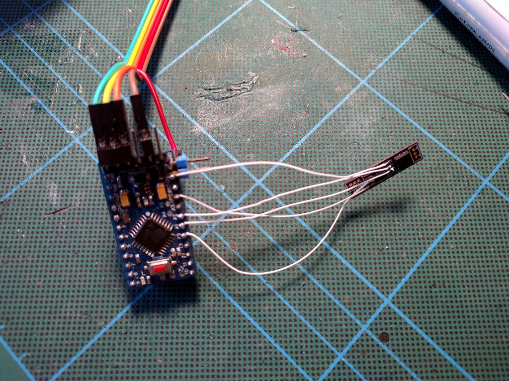
Note that the VCC cable from USB2TTL is connected to the RAW pin, not to the VCC pin on the FTDI header, because I don’t want 5V on the VCC pin…A quick sketch lets me verify that the thing works!
void setup() {
    Serial.begin(115200);
}

void loop() {
    Serial.print(analogRead(A0));
    Serial.print(", ");
    Serial.print(analogRead(A1));
    Serial.print(", ");
    Serial.print(analogRead(A2));
    Serial.println();
    delay(300);
}
Now I just need to figure out what are the center values when powered with the battery I want, and write the program.