Fixed Board
Published on 2016-01-07 in Tote Zero.
After some cosmetic touches, I’m finally happy enough with the first version of the PCB for this robot. It looks something like this:
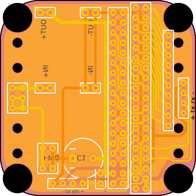
The Fritzing file is in the repository , and the Gerber is available for download. I used a new approach for the servo sockets – since the Pi Zero is going to be plugged as a second layer, we don’t really have enough space for the usual servo sockets. So I used one long header with angled pins – the servos plug in two rows into that, fitting between the Pi and the board.
Other than that, the board has the serial and I²C pins broken out, and also a header for all the pins that are not used for controlling servos. There is also a jumper in there, for disconnecting the servo power from the Pi – so that we can power the two from two different sources if we need to.
The usual holes, as in Tote, are for attaching the servo horns for the legs.