Use a Pro Micro in a Keyboard
Published on 2015-11-02 in Alpen Clack.
So you want to build your own keyboard (or keyboard-like device), but you are not sure what to use for the brains and how to connect and program it? I will describe what I came up with for the Alpen Clack keyboard.
The ATmega32u4 microcontroller is an excellent choice for any HID device, such a mouse, a joystick or a keyboard. That’s mostly because it has hardware USB support, so you don’t have to muck about with unreliable and hacky bit-banged VUSB. There are three popular boards with that microcontroller: Arduino Leonardo, Teensy 2.0, and Pro Micro (not to be confused with Pro Mini, which uses ATmega328). Arduino Leonardo is too big for our needs. Teensy 2.0 is quite expensive. Pro Micro can be had for about $4 in singles from the usual oriental sources. Sounds like a winner. Let’s look at the pinout:
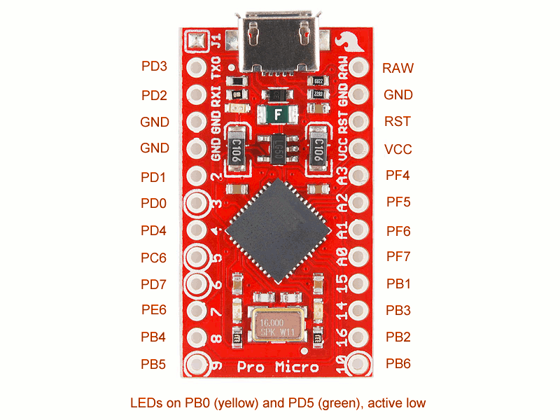
According to this diagram, we have 18 usable pins. An 18-key keyboard is not very useful. Can we somehow connect more keys? Turns out we can, by using a key matrix . We basically make rows and columns, and put switches on the crossings. Then we scan that repeatedly to figure out which ones are pressed. We add diodes, so that the pressed keys won’t interfere with each other. Simple.
So, with 18 pins, the largest matrix we can get is a square 9×9. That’s 81 keys. Hmm, that may be fine for those tiny, chocolate bar keyboards, but a modern PC keyboard has 105 keys. Even if we ditch the keypad, like I did in my keyboard, that only removes 17 keys. We are still 7 keys short!
Wait, what does it say about LEDs at the bottom there? Two more independent pins? Great, we only have to remove the two resistors and solder wires in their place, and we have 20 pins for our disposal. That gives us the largest matrix of 10×10, so 100 keys. Still not enough for the full layout, but should be fine for a tenkeyless keyboard.
Next, programming the thing. After a short search, I found the TMK Keyboard firmware, which is just perfect for our needs. All we need to do is to copy the “onekey” example keyboard, and modify the_config.h_,_ keymap.c_ and_matrix.c_files to fit our keyboard.
In_config.h_, we have to set the correct number of rows and columns. I used 8 columns and 11 rows in my keyboard, which gave me the 88 keys I needed (actually 87). You can also change some other options here and in the_Makefile_.
Next, the hard part –matrix.c. You will need to define four functions:init_cols, read_cols, unselect_rows_and select_row_. You can look at all the examples included in the repository to get an idea what they need to do. Basically,init_cols sets all the column pins in INPUT mode with internal pull-up resistors. It’s called once at the start. Next, the_read_cols_ function reads the state of all those column pins, and reports it as a single byte (or more, if you have more than 8 columns, but see below). The_unselect_rows_ function sets all the row pins to floating, and finally the_select_row_ function sets the specified row pin to low. That’s it.
One note about having more than 8 columns: while the code looks like it should support it, I didn’t manage to get that to work. I’m not too worried, because I only needed 8 in the end, but if you need more, you will probably need to copy the_matrix_scan_ function from one of the larger examples to get it to work.
Lastly, you need to define the key map – basically to tell the firmware which key is which. You do that in_keymap.c,_by defining an array of arrays of arrays… I mean, an array of layers, each layer being an array of rows, each row being an array of columns, each column being an array of keys. The layers let you setup cool effects with special keys and such, see the keymap documentation for details.
Lastly, we need to modify the_Makefile_ for our board. I used_Makefile.pjrc_, because the default one doesn’t support N-key rollover yet. Set the following variables:
MCU = atmega32u4
OPT_DEFS += -DBOOTLOADER_SIZE=512
PROGRAM_CMD = avrdude -p $(MCU) -P /dev/ttyACM0 -c avr109 -U flash:w:$(TARGET).hex
Now you are ready to program your board. Connect a switch between the GND and RST pins, connect the board to USB and press the switch two times quickly. That puts the board into programming mode. Now run “make -f Makefile.pjrc program”, and it should compile and burn the firmware to your board. After that it will be visible in “lsusb” command as whatever ID you set in the_config.h_ file, and shorting any row pin with any column pin should produce key presses. Now you can solder the board into your matrix, and you are done.