Matrix
Published on 2015-10-31 in Alpen Clack.
The favorite microcontroller for all things USB, such as keyboards, joysticks or mice, is the good old ATMega 32U4, well known from the Arduino Leonardo. Of course I don’t plan to stuff an Arduino-footprint board inside my keyboard, I need a smaller board. There are two popular small boards with that chip. One is the Pro Micro, the other is Teensy 2.0. I have some Pro Micros, which I purchased for around \(4, in my drawer just for the occasions like that. The keyboard modding community seems to prefer the Teensy for some reason, even though it's around \)15. Oh well, I suspected it was because it had a GUI uploader.
I was wrong.
It turns out that Pro Micro doesn’t break out all the pins. In fact, it only breaks out 18 GPIO pins, and uses 2 more for build-in LEDs, leaving the remaining 5 pins unconnected. Just take a look at the schematic:
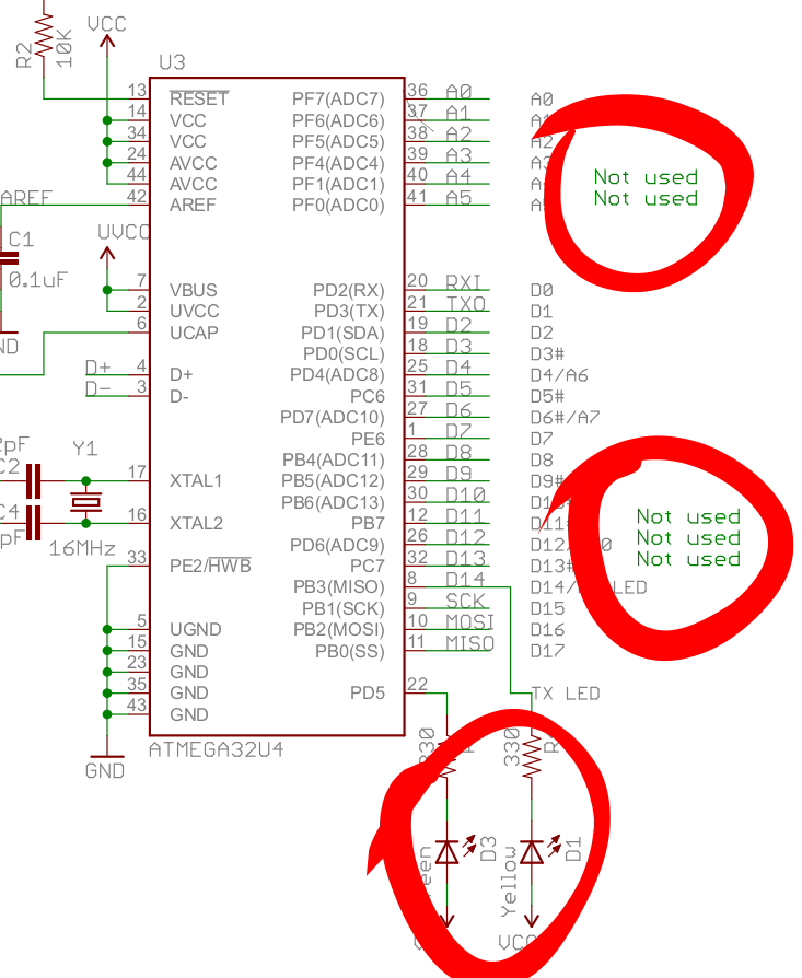
OK, with some delicate soldering I can reclaim the two LED pins – just remove the LEDs and solder wires in that place. That gives me 20 pins to work with. My keyboard has 88 keys. That means, that if I make a matrix 8×11, I can support them all with 19 pins, and even have one pin left for a LED or something. Yay. But 8×11 is not exactly how the keyboard looks physically – it’s more like 5.5×16 (some columns have 5 rows, some have 6). So, to get 8×11, I will have to transpose it and merge every two neighboring columns together. That’s doable, it just means I will have fun time converting the layouts.
Now, let’s look for some ready-to-use firmware, so that I don’t have to do all this coding myself (not that it’s very complicated, but I’m lazy). For that chip, this seems to be pretty popular: https://github.com/tmk/tmk_keyboard
First, I burned one of the example keyboards to the board with avrdude:
avrdude -p atmega32u4 -P /dev/ttyACM0 -c avr109 -U flash:w:gh60.hex
(you have to get it into the boot mode first by pressing reset right when it boots).
Then I connected some of the switches to some of the column/row pins, and pressed them – and voila, it typed some letters! So the firmware works great.
Next, I will have to modify it to support my particular keyboard layout, with this almost square matrix. Looking at the_matrix.c_ file in the examples, you can see code like:
/* Row pin configuration
 * row: 0   1   2   3   4
 * pin: D0  D1  D2  D3  D5
 */
static void unselect_rows(void)
{
    // Hi-Z(DDR:0, PORT:0) to unselect
    DDRD  &= ~0b00101111;
    PORTD &= ~0b00101111;
}
Hmmm…. Does that mean I need to have all row pins on the same port? I need 8 rows, so that would be doable… Let’s see… Nope. Whoever designed the Pro Micro, he or she left out a single pin from each port, so that no port has a complete set of pins broken out. Splendid. Let’s look at the other examples…
OK, I can pretty much write anything I want in those functions, all I need is to initialize the pins I want and read them all into a single number with something like:
static uint8_t read_rows(void)
{
    return (PIND&(1<<0) ? (1<<0) : 0) |
           (PIND&(1<<1) ? (1<<1) : 0) |
           (PIND&(1<<2) ? (1<<2) : 0) |
           (PIND&(1<<3) ? (1<<3) : 0) |
           (PIND&(1<<5) ? (1<<4) : 0) |
           (PINB&(1<<7) ? (1<<5) : 0);
}
Not very pretty, I bet I could write it nicer, but that should work.OK, writing it all and writing the layout definition is going to take some time, but at least I know how to proceed. See you at the other end.