Choosing the Brains
Published on 2017-01-11 in Tote.
In the previous post I shared some of my thoughts about this project, and decided to pick a different development board than the Pro Mini that I have been using so far. Don’t get me wrong, Pro Mini is great for all kinds of small and cheap projects, it’s just that I want to make programming this robot as simple as possible. That, among other things, means using a platform that has a lot of computing power, not just enough, preferably one that has so much of it, that it can be used with a high-level language like Python. That also means something that has a USB socket.
The plan is to keep the Tote base PCB for its body, and keep the ATmega microcontroller on it, but make it only serve as a servo controller. Then, on top of it, have headers for plugging in the actual brains, and possibly for stacking additional shields with sensors and other peripherals. The board would only need connections for the power and the I2C pins, but since there is no standard for the pin layout (or, rather, there are lots of standards), I need to choose one – history shows that trying to make it flexible and compatible with many different boards only leads to pain and suffering.
However, I still want this to be relatively cheap. It would be bad if the brain was more expensive than the ~$20 the legs cost. I first tried with the D1 Mini board, because it’s my favorite ESP8266 board, it’s small and compact, and it has a number of shields for it available. It’s also easy to make new shields for it, and they can be very small, which makes them cheap on OSHPark. The board can run MicroPython and has WiFi build in, which makes it easy to use a remote console to program and debug it very conveniently. There is also a LiPo shield, which makes it possible to recharge the battery from the USB. So I spent some hours making this:
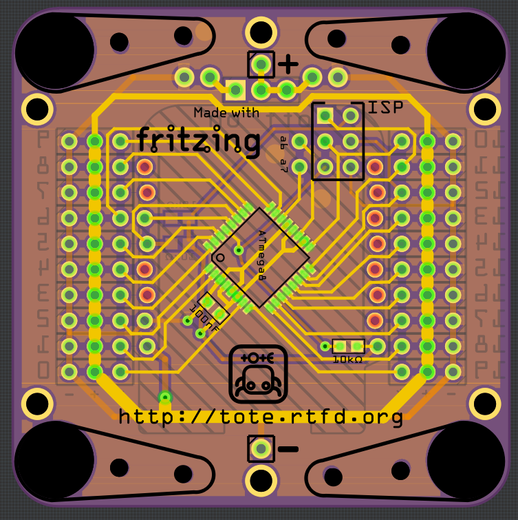
The base is just the Servo Breakout for WeMos D1 Mini with 20 channels for the servos. I tried to make it easier to reprogram by including the ISP header. There are no Tote-specific markings about leg servos and so on there – just channel numbers, so it makes it easier to see which servo is which inside your program, where you have to refer to them by numbers too (at least initially). This way there is no hardcoded magical knowledge necessary, and you can use the remaining 8 PWM outputs for other things, or use this board with a different legs configuration than Tote has.
There is also a power switch in there, but it’s not connected to the rest of the board – since I didn’t decide about how it will be powered yet (you can have the LiPo shield or not, you can have some other charging/protection module, you can use a powerbank, etc.), I left it disconnected and only provided headers. I also added battery connectors on both ends of the board, for use with any battery holder. Unfortunately, I didn’t know which one, so I just spaced them as far from each other as possible.
Then there are the headers for connecting the D1 Mini and its shields. I used alternating holes headers, so that you can plug it directly into the PCB (but you can also use headers). I connected the servo power to the 5V pin, to bypass the voltage regulator on the board.
Later, I found a tube of ATmega328 chips in the MLF package, and I was a bit bored, so I made a version for that, playing with Fritzing’s curvy traces:
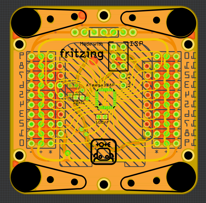
It was fun, but ultimately unproductive. Anyways, I liked the first board, so I ordered it at DirtyPCBs and went do bed.I couldn’t sleep that night.
Tossing and turning, I started thinking about different options I have for using this. Then the doubts crept it. If I use the LiPo shield, there will be a boost converter on the 5V line that powers the servos. Will it have enough power for all those servos? If not, can I somehow power the servos directly from the LiPo? I don’t have a connection for that on the board, should I add it? What will happen if I short the 5V pin with the 3.3V pin on the D1 Mini? Will that damage the voltage regulator? Can I make adapters for the D1 Mini pinout for other boards? What if I wanted to use OpenMV, could that work? Which of the official D1 Mini shields would actually be useful? The temperature and humidity sensors? The button shield? The single WS2812B RGB LED? Will there be enough room between the robot legs to place the board under the body instead of on top? And so on.
Finally, at 5am I decided I’m not going to fall asleep anyways, so I could as well do some mock designs. What other ESP8266 development board do I know that has a lot of shields available? Maybe the Adafruit HUZZAH Feather? It’s a bit expensive, but it does come with a LiPo charger built-in, the correct pin markings for MicroPython (the D1 Mini uses the NodeMCU markings) and generally has great support. There are also other Arduino-compatible boards with that footprint, and there is an M0 board that also runs MicroPython. And the shields somehow look more appealing.
So I decided to give it a try, and I came up with this:
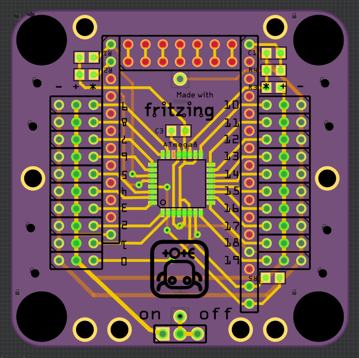
Unfortunately, the Feather is a fraction longer than the 5cm of the Tote’s base, so it sticks out about 2mm in front. That’s where the ESP8266’s antenna is, so I guess that’s fine. I also made a couple of other decisions here.Since there is no boost converter, only the charging circuit, I have no problems with servos drawing too much power – I will just power them directly from the battery. I decided on the kind of battery to use – I discovered the 16340 lithium batteries. Previously I knew the 18650, as they are commonly used for power banks, but those are too big for Tote. The 16340 is half that size, and there are convenient battery holders for it. So I added holes for mounting such a holder on the bottom of the board, and made all the connections for the switch and the charging circuit, etc.
I also decided to use one of the analog-only pins of the ATmega for battery voltage monitoring, since I wasn’t using them anyways. It’s the same voltage divider circuit I had in the previous Totes.
One more addition, is the double pin header on the front. I plan to add a female header to it, but soldered flat on the board, so that you can easily plug any sensor breakout boards into it, and they will be facing forward. Of course, you would need to make any connections with additional wires, but at least there is the mechanical support.
But something wasn’t quite right. I had this nagging feeling that I’m forgetting something. I reviewed my notes, and then I realized. Tote is supposed to be simple to build without access to special tools like 3D printers or laser cutters. Or like reflow ovens, hot plates, hot air guns or very precise soldering irons, like the one I have. I have SMD parts on that board, and no beginner is going to solder that with a cheap soldering iron, without using any flux. This board is simply too complex for Tote. I need something simpler.
So I deleted the microcontroller and all the SMD parts, and started working again. I came up with something like this:
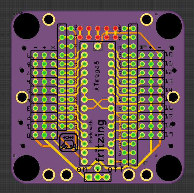
There is a number of changes. I used an ATmega chip in a DIP package, which should be easy enough to solder with a rusty nail. There are no analog-only pins in that version, so the battery monitoring went away. I connected the reset pin to the Feather’s reset, so they share the pullup resistor there. And I’m going to use internal pullups for the I²C lines.\
Next, I aligned all the headers with each other, so that it’s easier to solder them all by inserting them into a breadboard for holding. I had some room on the sides, so I doubled the Feather’s pins, making a prototyping area where you can connect those wires from your sensors, or whatever you want. I also disconnected the second ground pin from the ground, as I realized that it’s connected to CH_PD on the HUZZAH, and I would get a short there. As a finishing touch, I added all the labels I could think of, and moved them to more convenient places. I also added ground fill and some silkscreen decorations that are not shown here, for clarity.
DirtyPCBs has this awesome feature, where you can change your order’s gerber if it wasn’t assigned to a panel yet. I checked my order, and it wasn’t, so I quickly swapped this. I think this is the design I’m going to go with. It’s easy enough to assemble even for a beginner, provides a lot of room for prototyping, and is simple and modular.
It’s funny how bigger components, like the DIP chip and the Feather board, actually give me more room on the board. The DIP chip has much better spacing of the legs, so I don’t need as much width for fitting all the traces. The Feather is narrower than the D1 Mini by 2.54mm, but that means you can fit two Feather shields (they call them Wings) on a 5x5cm PCB, and you have room for the servo horns on the sides of that base board. Finally, you can use a DIP socket and make the chip pluggable – so you can easily replace it, and also reprogram it more conveniently.
I’m really excited about this board, and I think this is really the right direction for Tote to go in. The next step is code and documentation for it. If the prototype works well enough, I’m going to make it the default version in the documentation and only focus on this. Can’t wait for the boards to arrive.