Testing The New Printed Circuit Board
Published on 2015-07-21 in Tote.
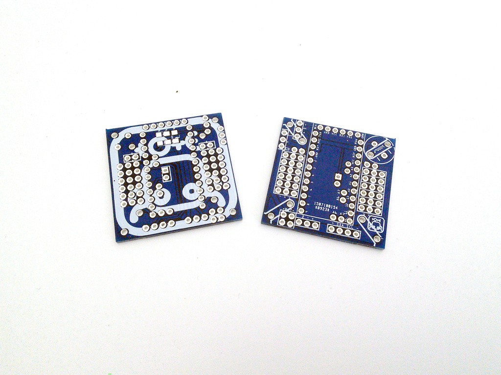
The new PCBs just arrived from Dirtypcbs and I started to test them. This is version three of the board, and most of the improvements are really just for convenience or aesthetics .

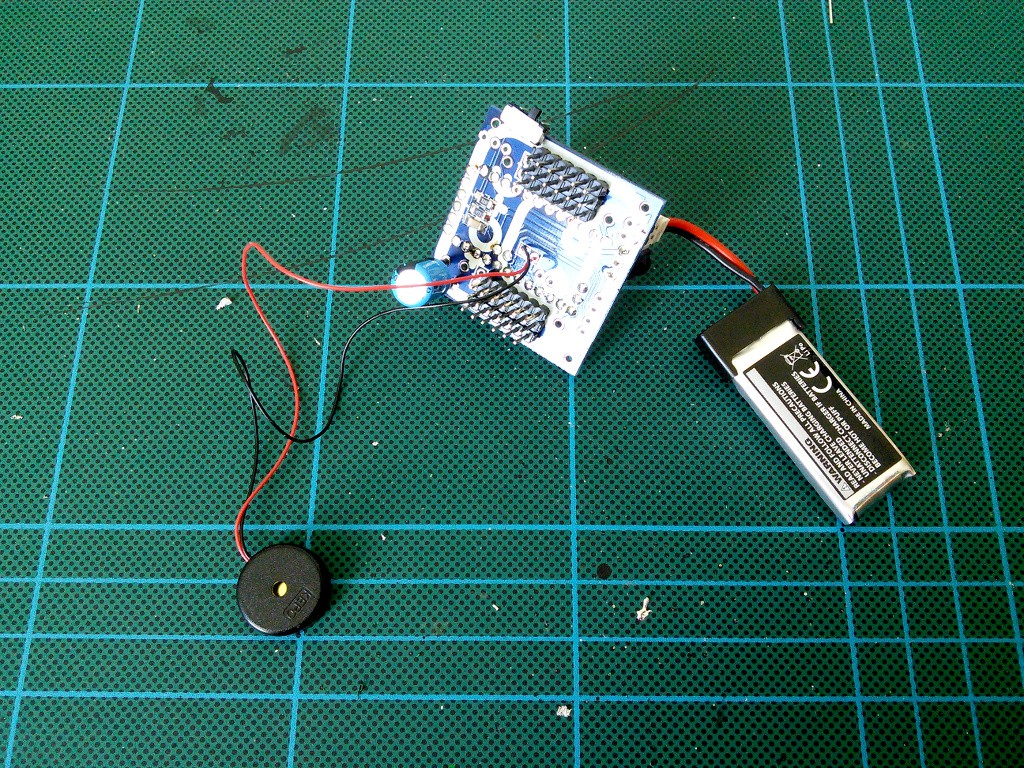
So, this time there seem to be no errors on the board (last time I got boards with solder mask applied to some of the SMD pads). The picture doesn’t really look as good as I hoped, but that’s fine. Time to assemble the electronics and see if the robot works:\

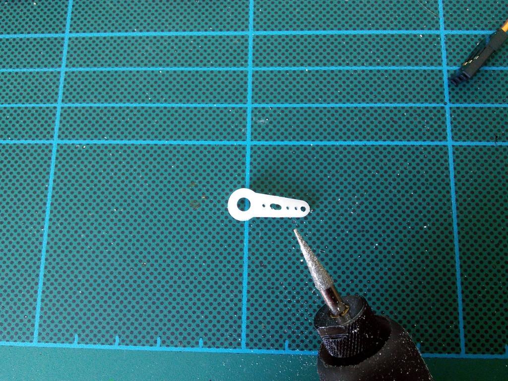
Along the way I also made a lot of photos, so I will probably be updating the assembly manual with them soon.Once I started to add the servomechanisms, I noticed that the mounting holes on the board are spaced wrong for the servo horns that I have. Strange. I compared them with the previous boards, and the holes are spaced the same. So it’s the horns. Turns out that those cheap servos come with wildly varying horns, depending on where you order them and what batch they are from. I had to modify mine a little:

The next version of the PCB will definitely have to have the holes spaced a little bit farther apart, so as to be closer to the average for those horns. I think I will also make the holes a little bit larges, so that you don’t have to use so much force when screwing in the screws. Lastly, while moving the battery connector was a good idea, the switch is still in an inconvenient place next to a leg. I wonder if I could place it better somehow.
 deshipu.art