µBob biped robot
Two legs, four servos, ATtiny85 for brains
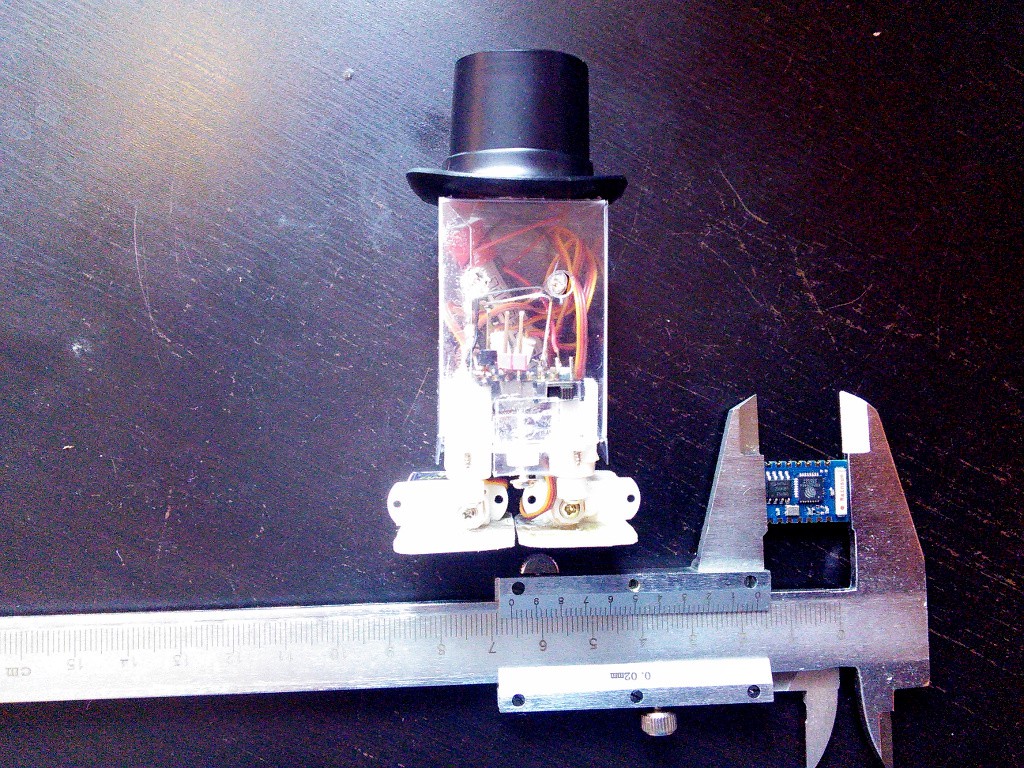
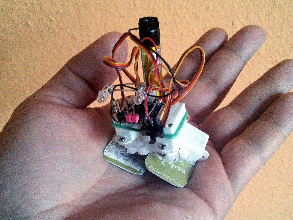
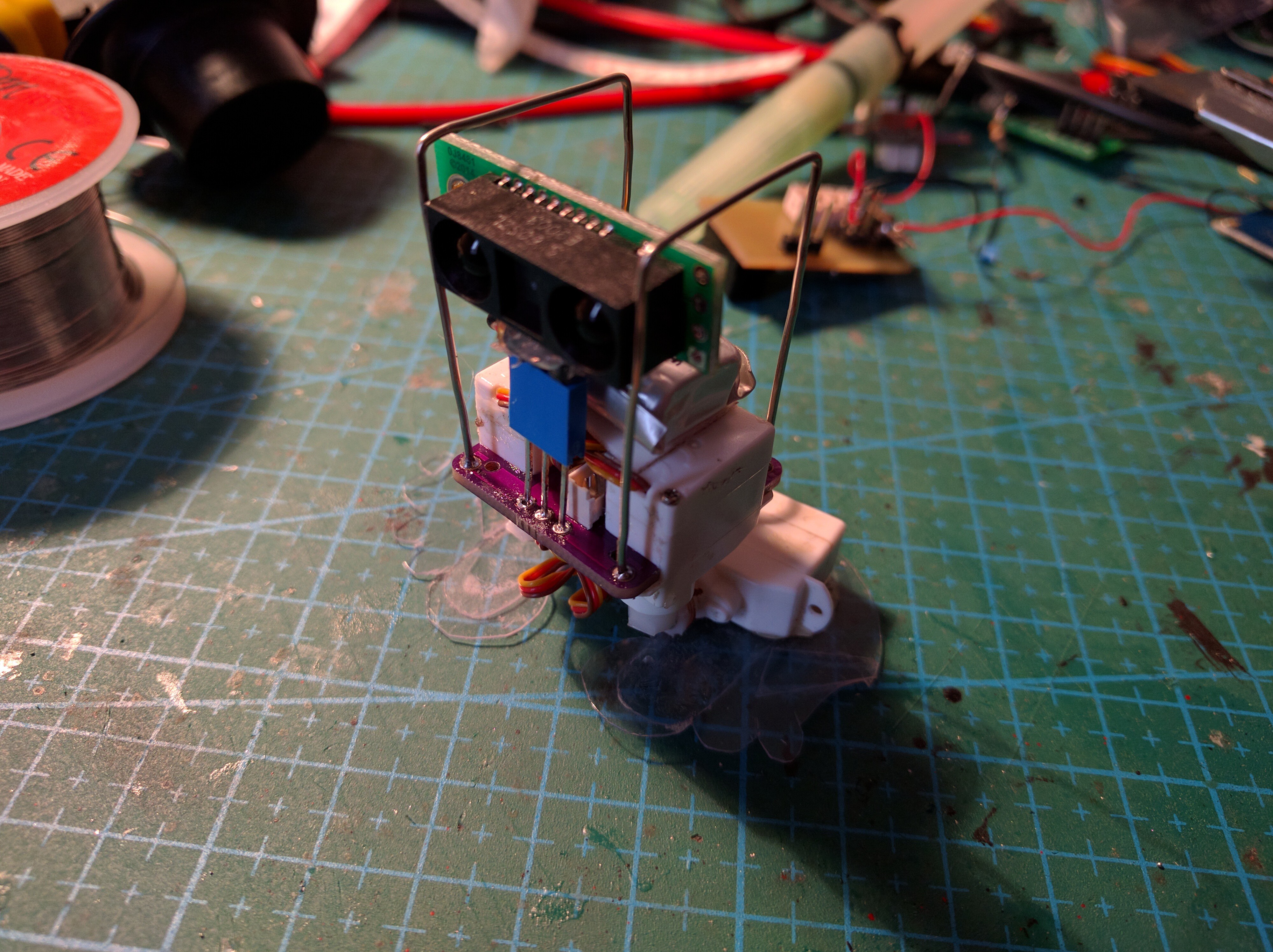
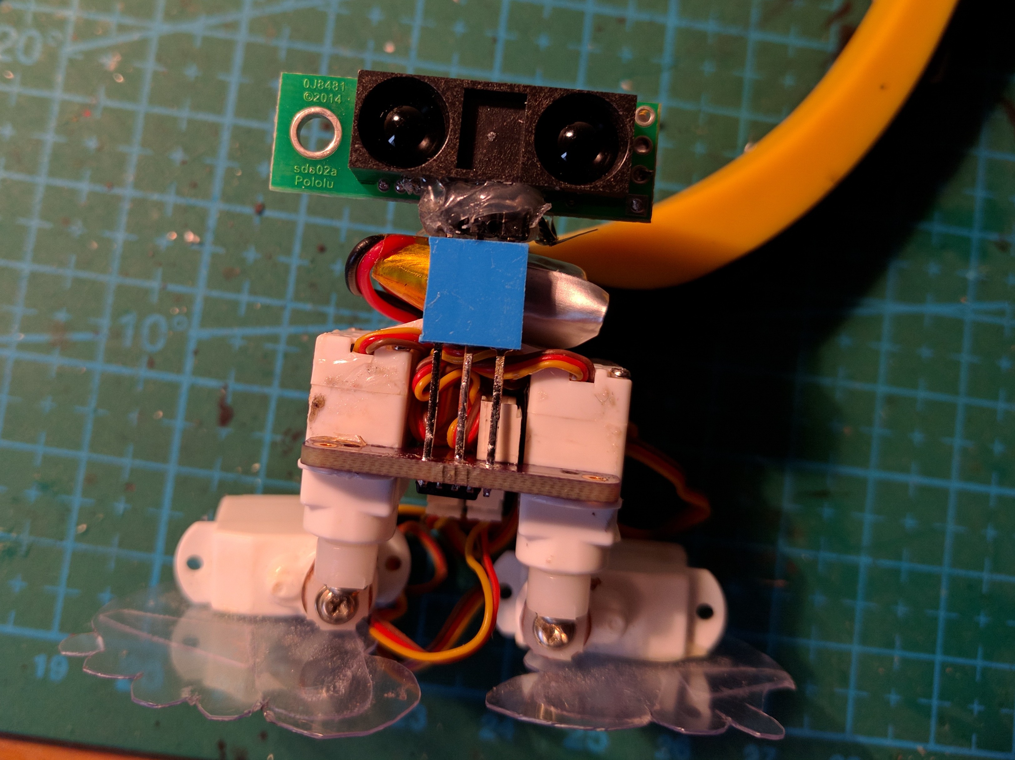
This is a tiny, minimalist version of a popular biped robot design. I used tiny hobby servos, a very small lipo battery, a SHARP distance sensor and an ATtiny85 (previous version used an ESP8266 module).
Logs
2017-01-01 - Obstacle Avoidance
2016-12-31 - Distance Sensor
2016-12-30 - The Body
2016-12-29 - Ressurection
2015-08-13 - ESP8266 Servo Breakout Board
2015-06-25 - Second Try on the Sensor
2015-06-05 - RIP ESP-12
2015-06-04 - Second Chance
2015-06-04 - PCB Fun
2015-04-17 - Not Feeling Well
2015-01-21 - My First PCB
2015-01-18 - Schematic
2015-01-16 - Onward!
2015-01-15 - Began Coding
Links
Components
Component |
Count |
Notes |
|---|---|---|
HK15318B ultra-micro servo |
4 |
|
ATtiny85 |
1 |
Microprocessors, Microcontrollers, DSPs / ARM, RISC-Based Microcontrollers |
1S LiPo Battery |
1 |
|
Power Switch |
1 |
|
Piece of Plastic |
1 |
|
PCB |
1 |
Electronic Components / Misc. Electronic Components |
Pololu GP2Y0A60SZLF carrier board |
1 |
Instructions
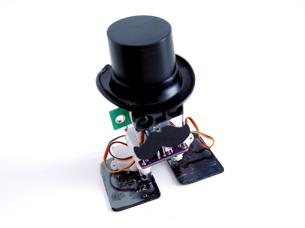
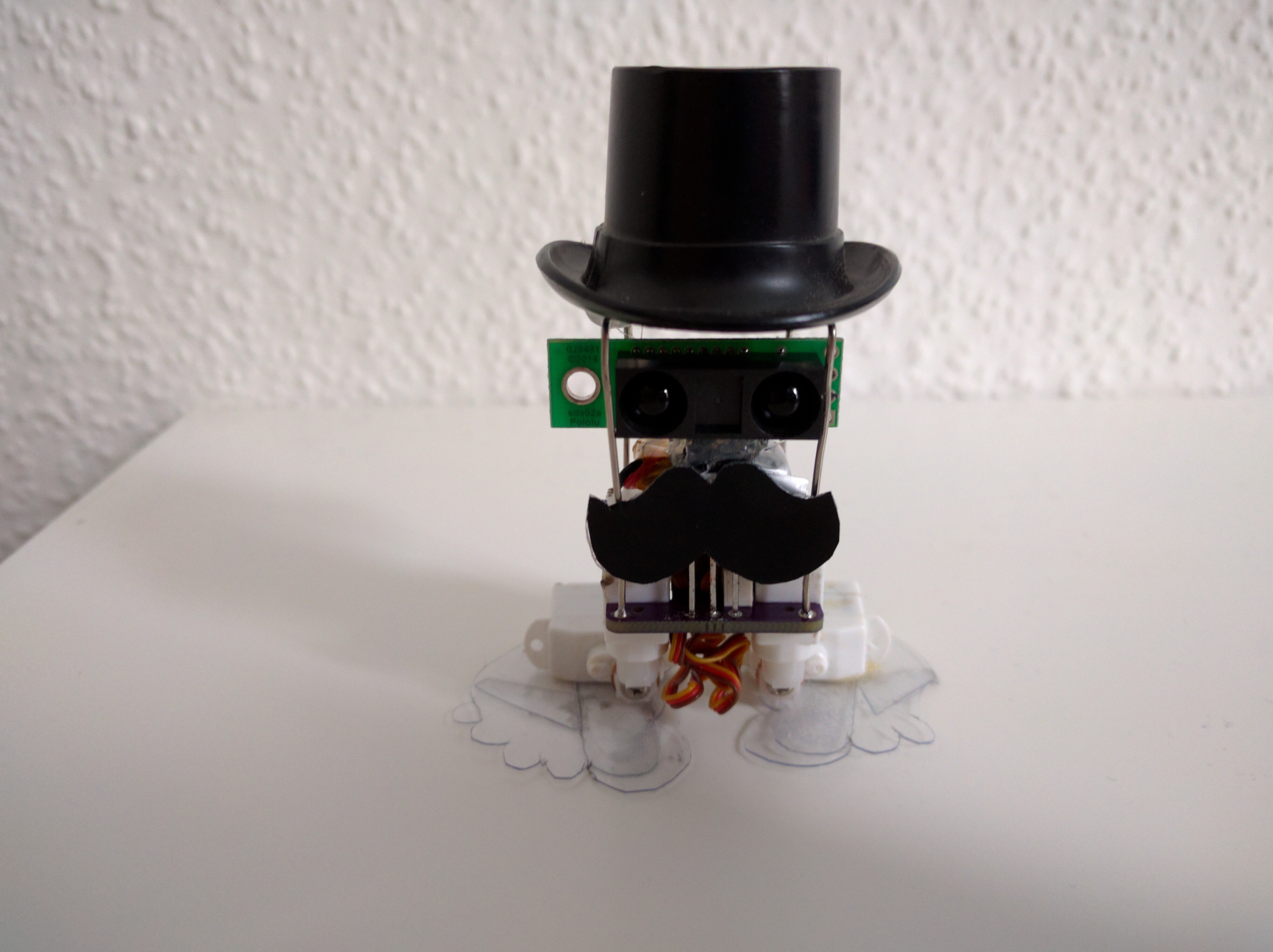
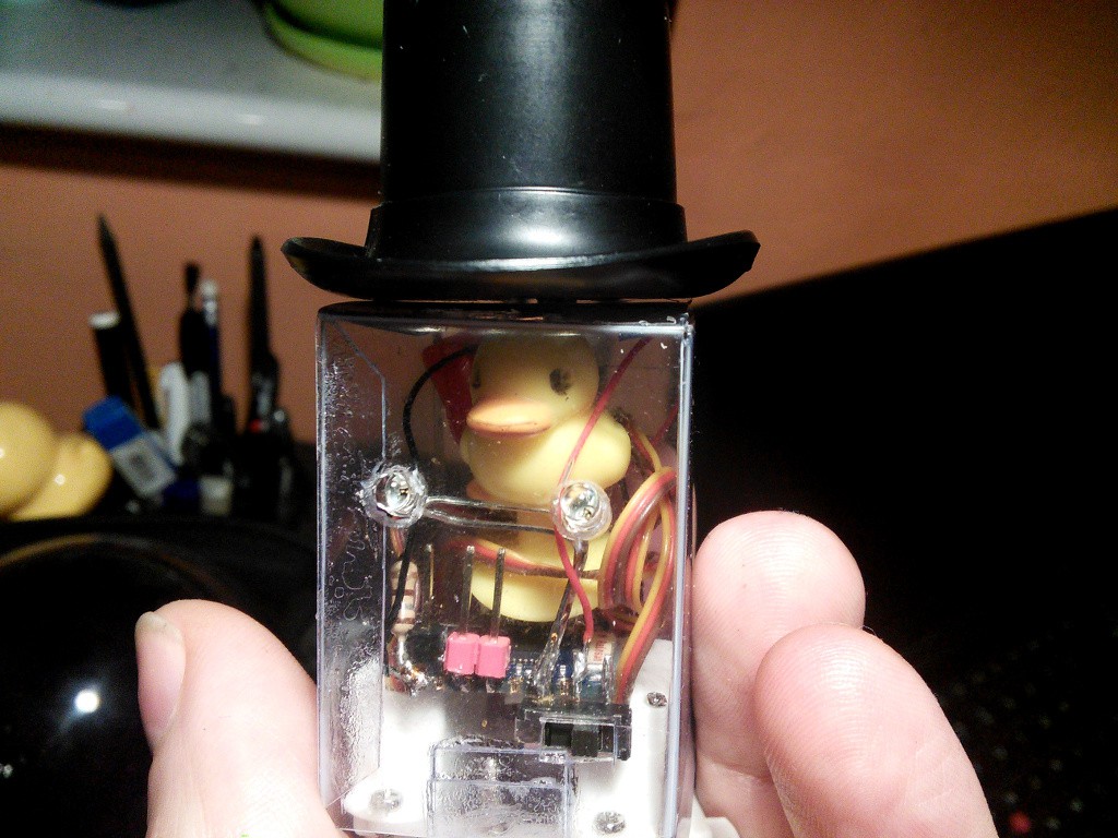
You can add a hat, a mustache, some wire hands, perhaps a pipe or a monocle, etc. The battery is attached to the frame with some two-sided tape.
First, you will need a PCB. There is a Fritzing file in the repository, which you can use to generate the gerbers and order it, and here is an OSHPark order you can use: https://oshpark.com/shared_projects/qjZ6fhAS
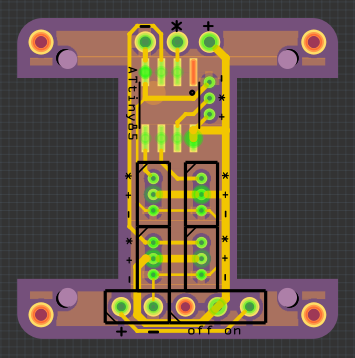
Once the PCBs arrive, you have to cut all the excess pieces, and polish the resulting irregularities. Depending on the servos you have, you might also need to file the PCB a bit to make them fit well. My servos fit exactly right, with some force, but you never know.
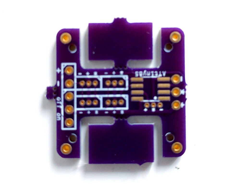
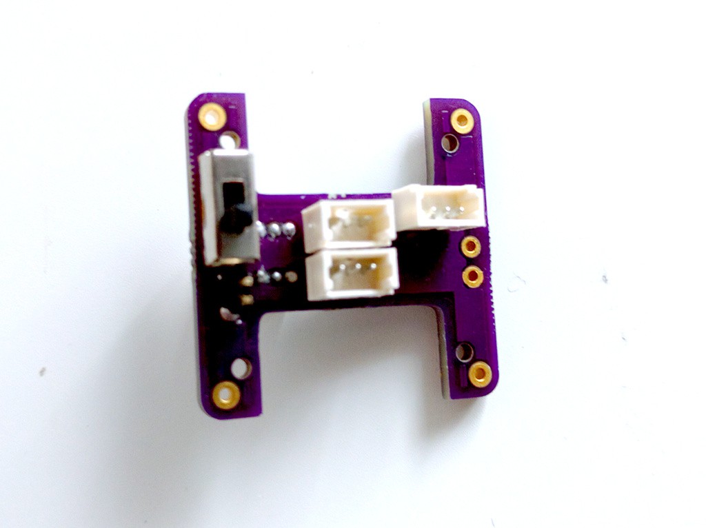
Assemble the PCB – solder the switch, the power socket, the servo sockets, the chip. Make sure to put two of the servo sockets on one side, and two on the other side – so that you don’t have to move wires through the PCB.
\
Before you attach the servos, program the chip using a programming clip. You will need to remove and disconnect the servos each time you are reprogramming it.
Assemble the legs. To make knees, take two servo horns, heat them with a lighter, and press them together – they will fuse. Make sure you make something like this:
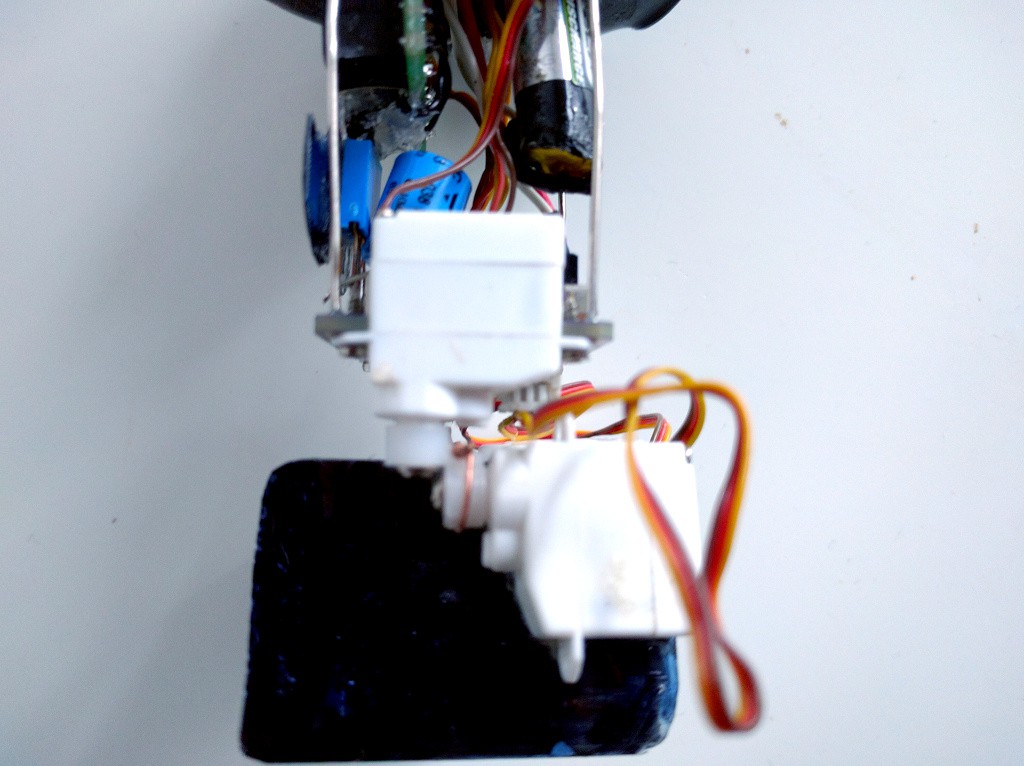
The feet are cut out from a piece of plastic and simply glued to the leg servos.
For the distance sensor, use hot-glue to add a 3-pin header to the bottom:
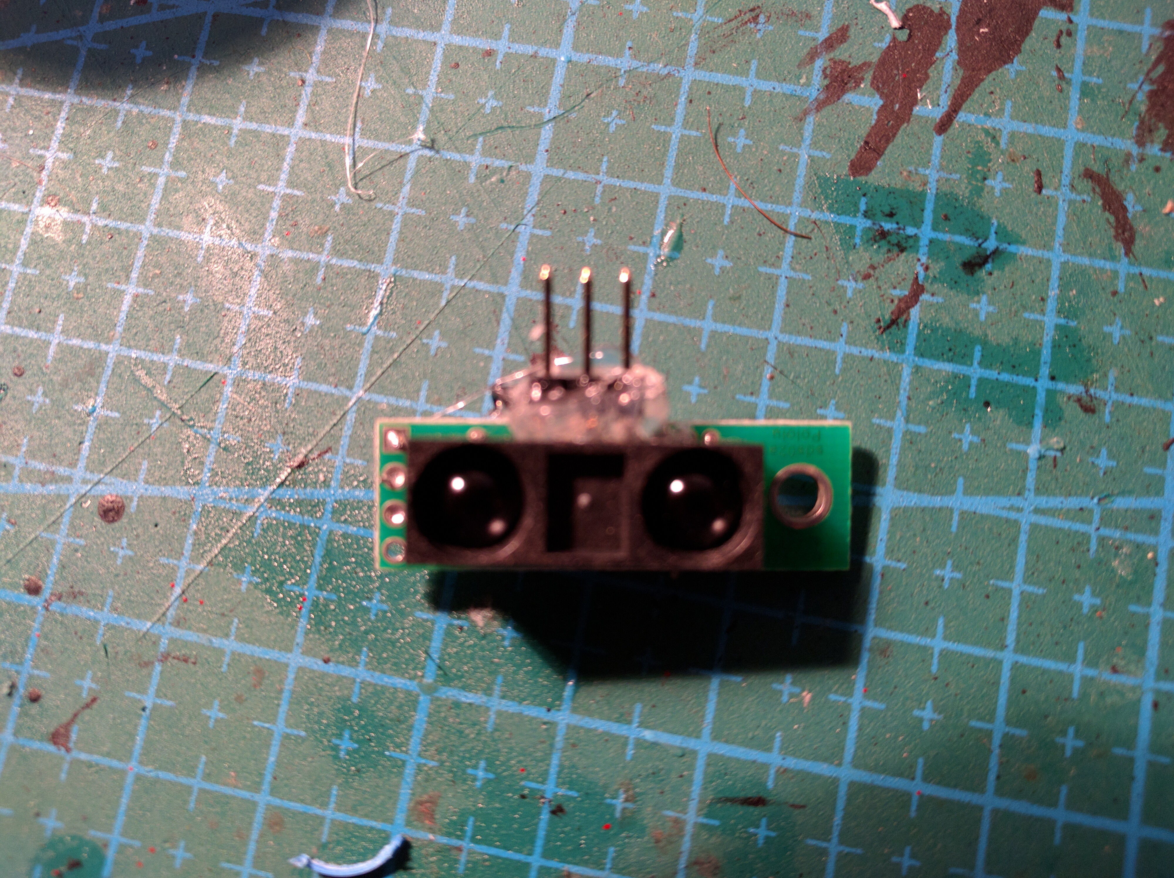
And connect those pins with short wires to the sensor’s contacts.
Then use a stacking header to attach the sensor to the PCB:
For the body frame, bend some paper clips and solder them into the holes in the corners of the PCB: