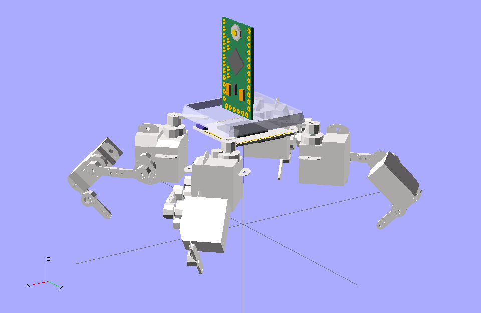
Pico-Kubik quadruped robot
The tinniest Arduino quadruped robot.
Logs
2015-03-02 - Battery Life
2015-02-26 - Exploring Under the Table
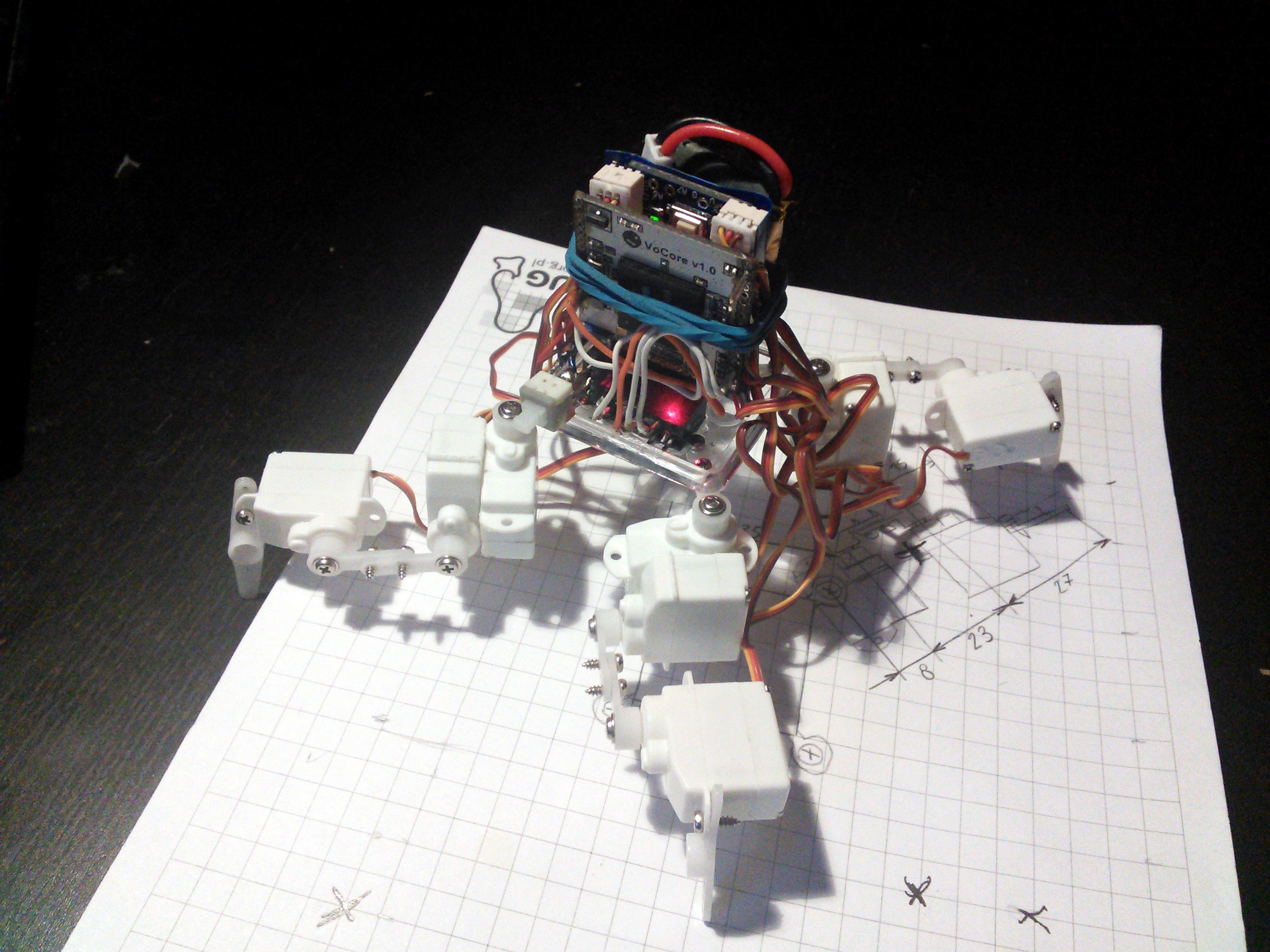
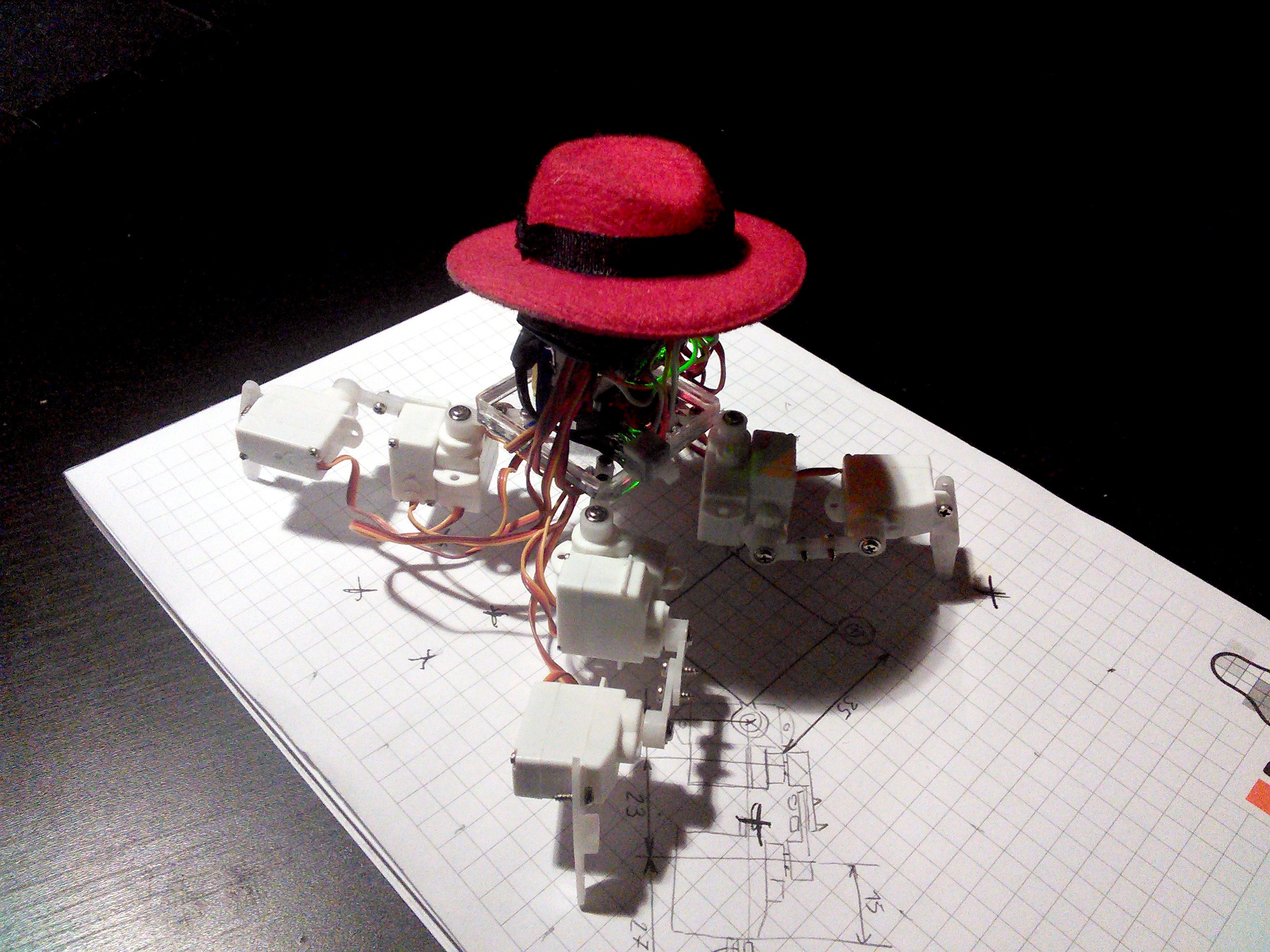
2015-02-25 - VoCore Version Rebuild
2015-02-23 - Minimal Version Improved
2015-02-22 - Minimal Version
2015-02-13 - Still Alive
2015-01-29 - Boards arrived
2015-01-29 - A Twin Brother
2015-01-14 - My First PCB
2015-01-08 - Camera Works!
2015-01-06 - Autonomous Walk
2014-12-23 - More Blue Smoke
2014-12-06 - Rubber Paint and Blue Smoke
2014-12-05 - New Camera
2014-11-25 - Everything Connected
2014-11-24 - Walking Controlled from PC
2014-11-22 - VoCore+Webcam
2014-11-19 - Startup Sequence
2014-11-19 - Servo Controller
2014-11-17 - Vocore
2014-11-13 - PyBoard
2014-11-02 - Deciding on the brains
Links
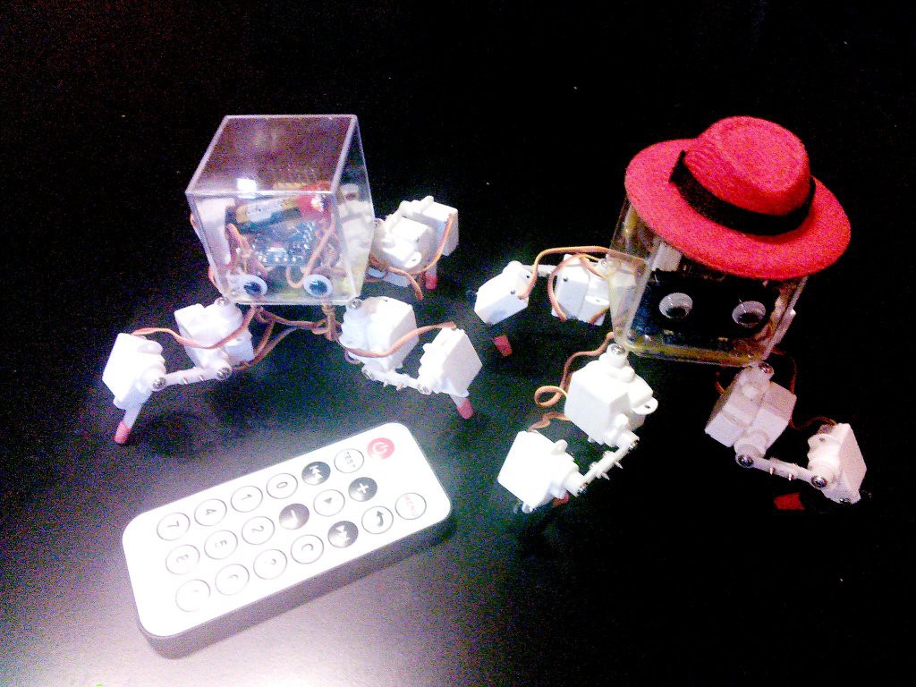
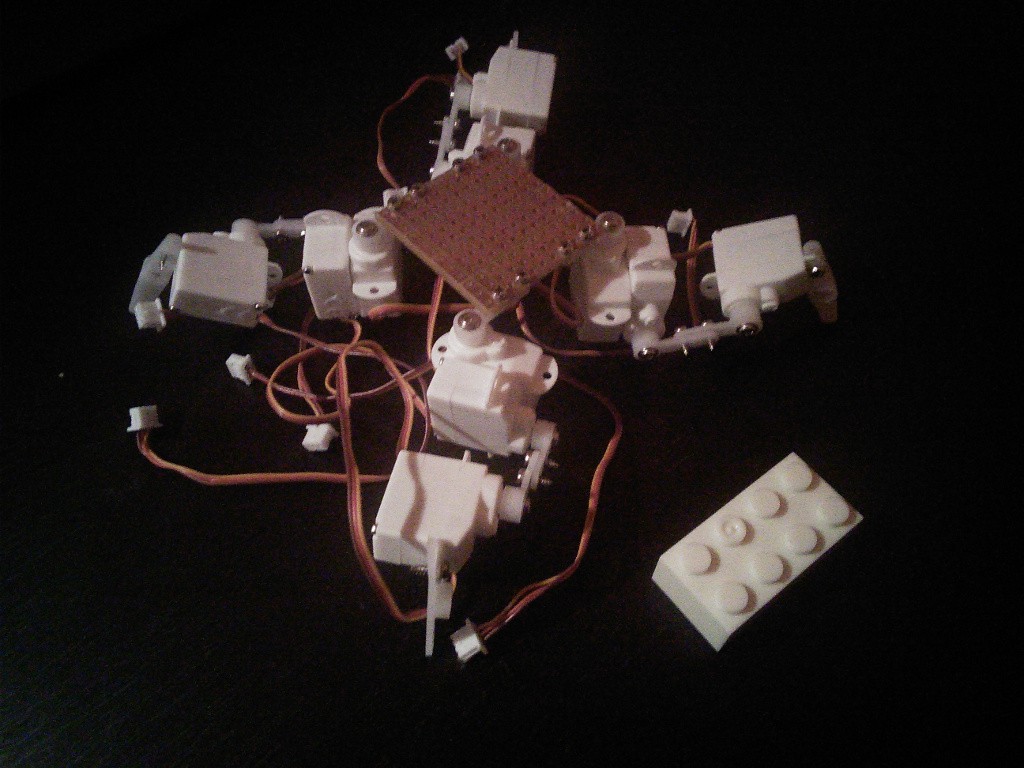
Components
Component |
Count |
Notes |
|---|---|---|
HK-282A Ultra-Micro Servo |
12 |
|
1S LiPo battery |
1 |
|
Arduino Pro Mini 3.3V |
1 |
|
PicoBlade Sockets |
12 |
|
VoCore 1.0 |
1 |
|
Power Switch |
1 |
|
Toshiba 8071_A2_GB Webcam Module |
1 |
|
1000µF capacitor |
1 |
|
47kΩ SMD resistor |
2 |
|
47nF SMD capacitor |
1 |
|
IR receiver |
1 |
Instructions
You can connect additional hardware to the free pins of the Arduino. For example, my robot has a VoCore board running Micropython, and talking to the Arduino over a serial connection. You can also use PyBoard, or Teensy 3.1, or even ESP8266 when it actually has a usable Micropython port.
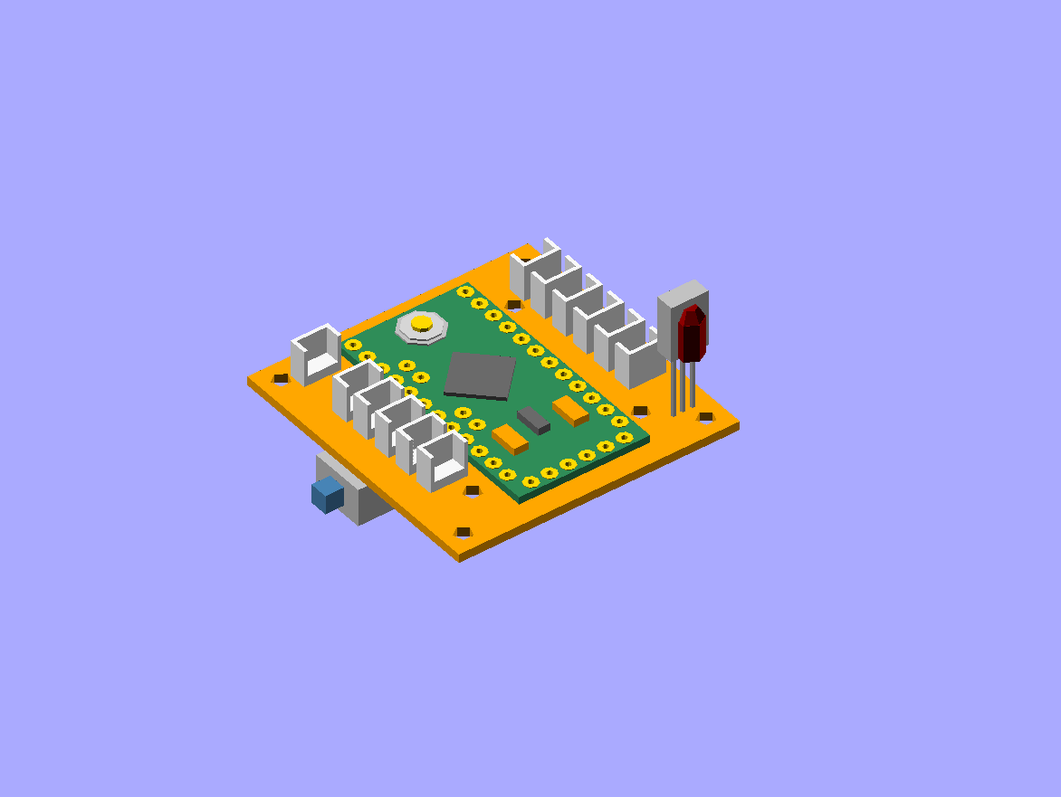
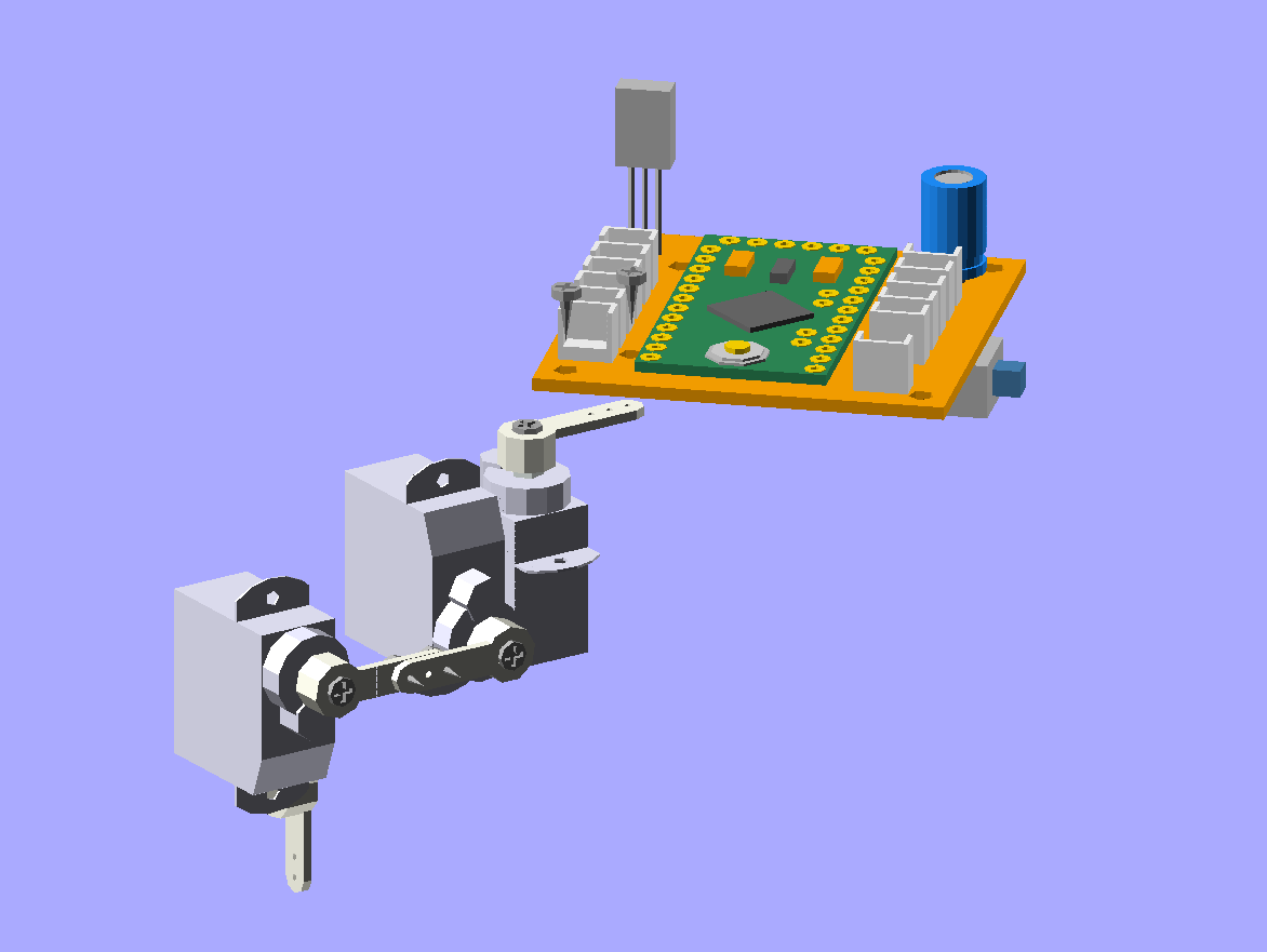
Solder all the electronic components, except for the capacitor, onto the printed circuit board. Make sure to make the right connections: the servo plugs should go with the yellow wire towards inside, and the brown towards outside, and the IR sensor may have a completely different order of legs than on the board, you might need to bend the wires a little to get them in the right order.\
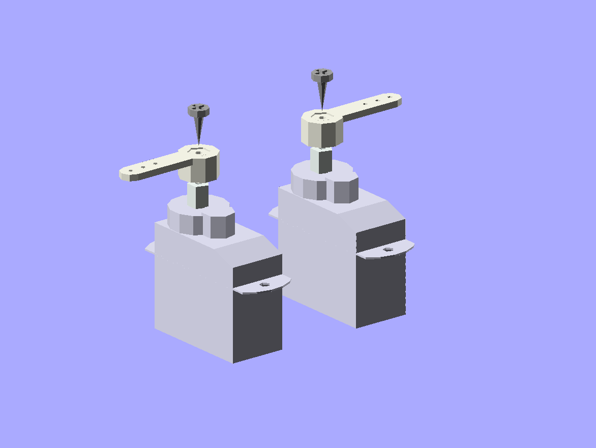
Set all the servos to the zero position (in the middle of their movement range). Then attach the single-arm horn at 90°. You will need six servos with the horn in one direction, and six servos with the opposite. Fasten the horns with the smallest screws (make sure you un- power the servo before you do that).\
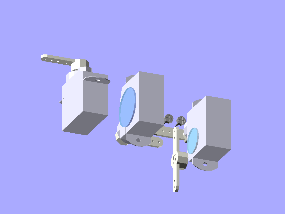
Put the legs together. You will need two right legs, and two left ones, that are their mirror images. Use the bigger screws to screw the servo arms together. Use glue to attach the double-armed horn and to bind the two servos.\
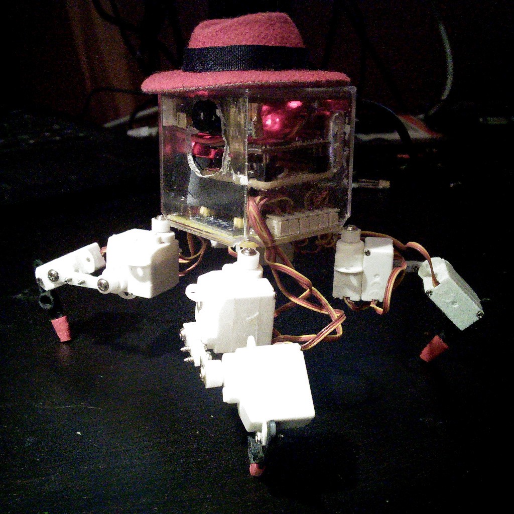
Attach the legs to the body, also using the bigger screws. You will need to make an additional hole in the servo horns. Make sure to attach the right legs in the right orientation, as on the image.\
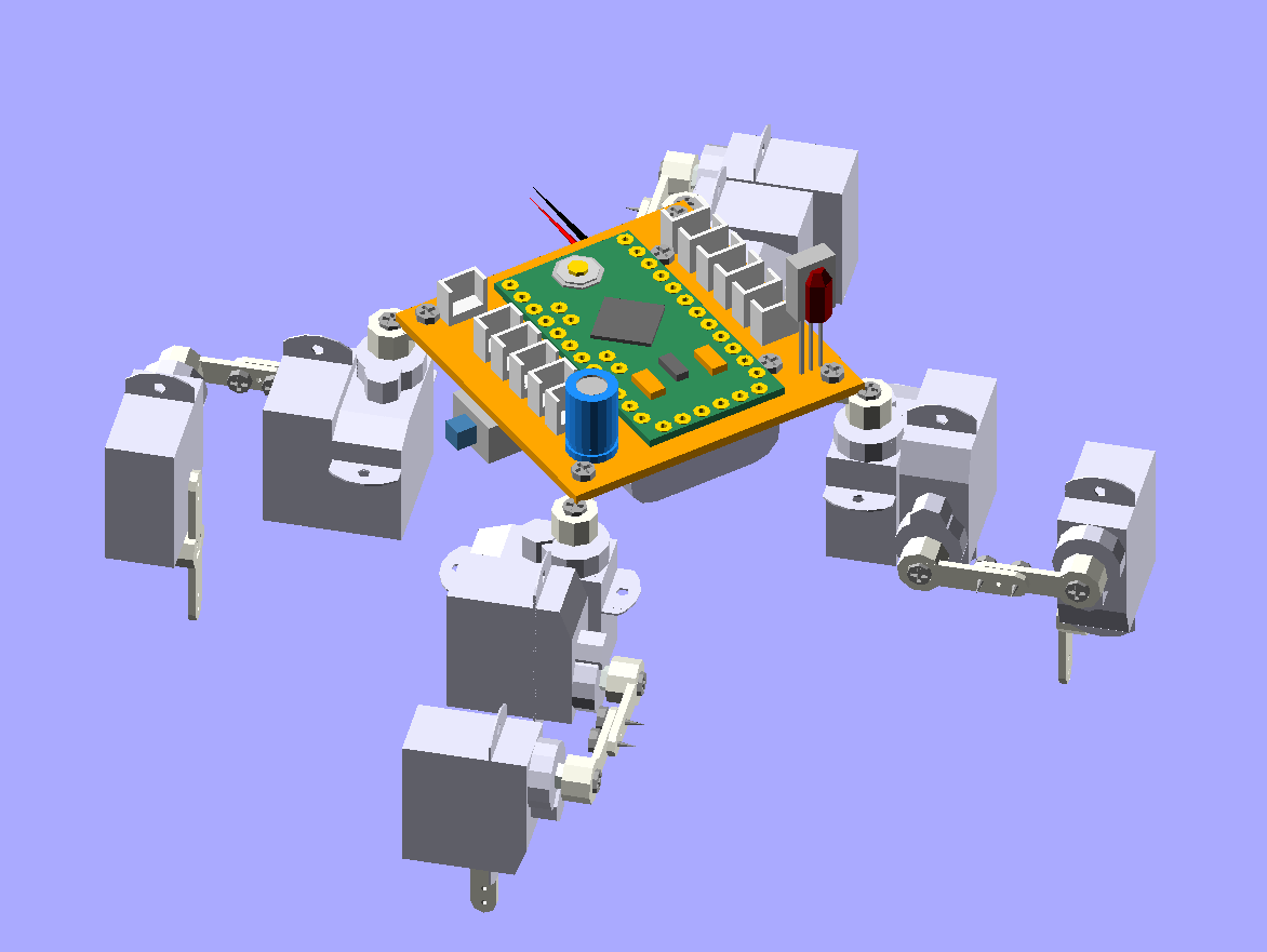
Connect all the servos plugs into their respective sockets. The outermost socket for every leg is the hip, then knee, then ankle. Solder the capacitor, making sure the negative lead is on the inside of the board. Attach the battery on the bottom of the printed circuit board. You can use a rubber band or a double-sided adhesive tape. When connecting the battery, be careful to connect the negative wire to the board’s mass, and the positive one to the switch.
Connect your TTL2USB programmer and upload the software using Arduino IDE. When you switch it on, it should start walking.
You can edit the_servos.ino_ file to adjust the trims for the servos. Edit the_ir.ino_ file to change the TV remote protocol, address and button codes, to match yours. You can use the example code from the IRLremote library to read the correct values for your remote.