Homebrew
Published on 2017-11-25 in µGame.
This device I’m building is not very beginner-friendly. It uses all SMD components, a bare displays screen, needs you to flash the bootloader to a bare chip and compile your own CircuitPython, etc. Quite a bit of work, to be honest. On the other hand, I would like the software library I’m making for this to be generally useful, and not just limited to this one device. So I wrote it in a way that lets you use it with pretty much any SPI display with 16-bit colors, and any buttons. Today I went and made a “homebrew” version of µGame, to show that it really doesn’t have to be hard.
My initial experiments used a Trinket M0, but to really write an interesting game you will probably need much more room, so this time I used a Feather M0 Express, which has an additional flash chip. I also used a breakout board I made for displays, and a bunch of buttons:
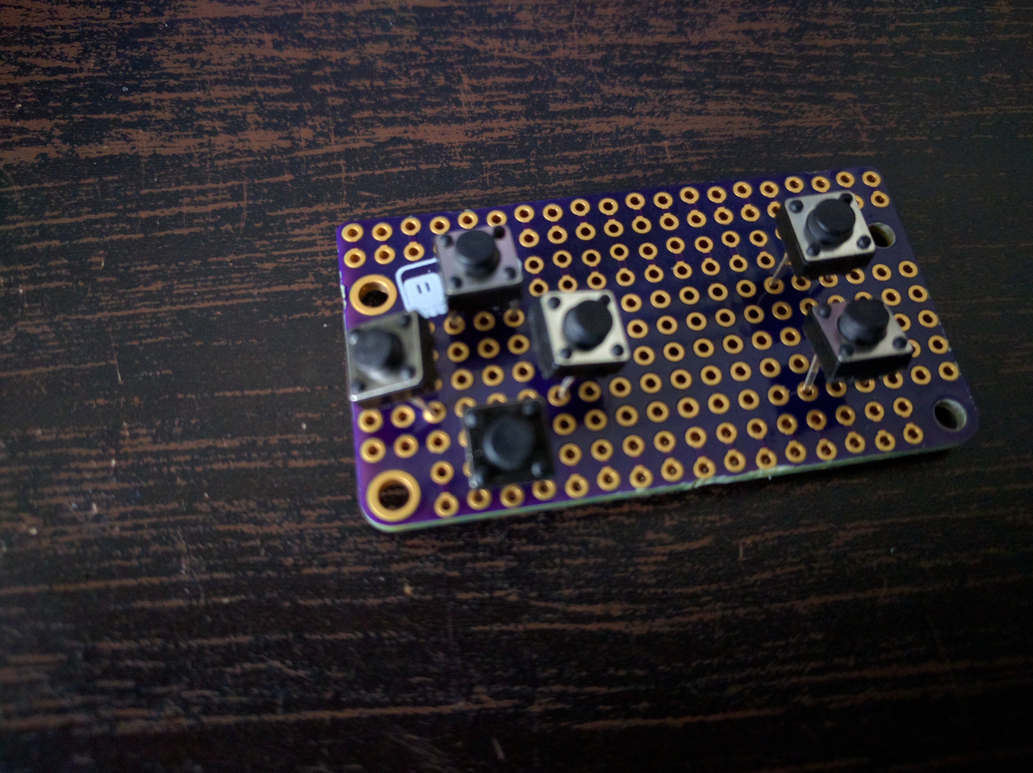
———- more ———-I had to bend the legs of those buttons a little bit, to pack them on the board tightly enough:
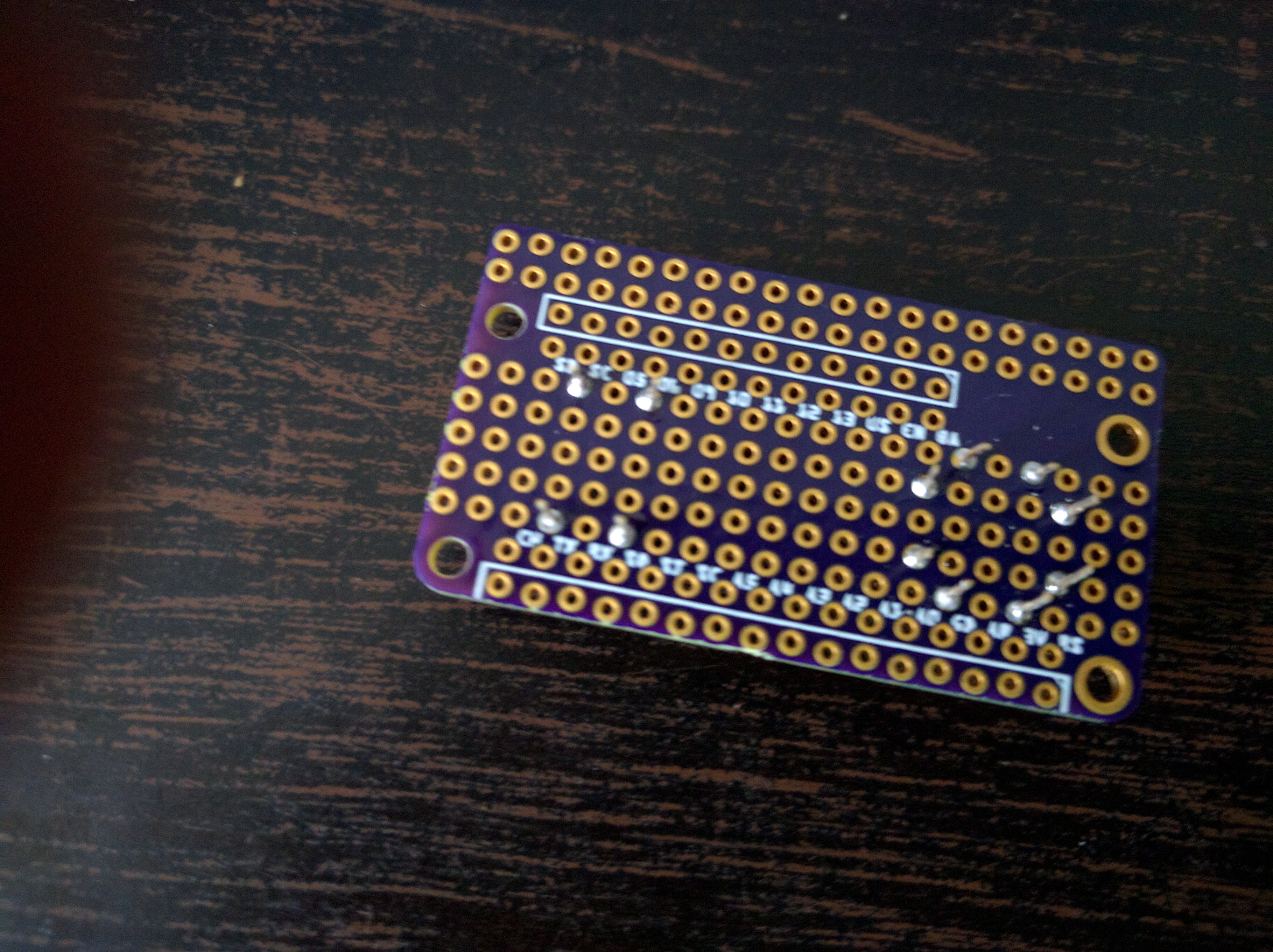
A little bit of soldering:
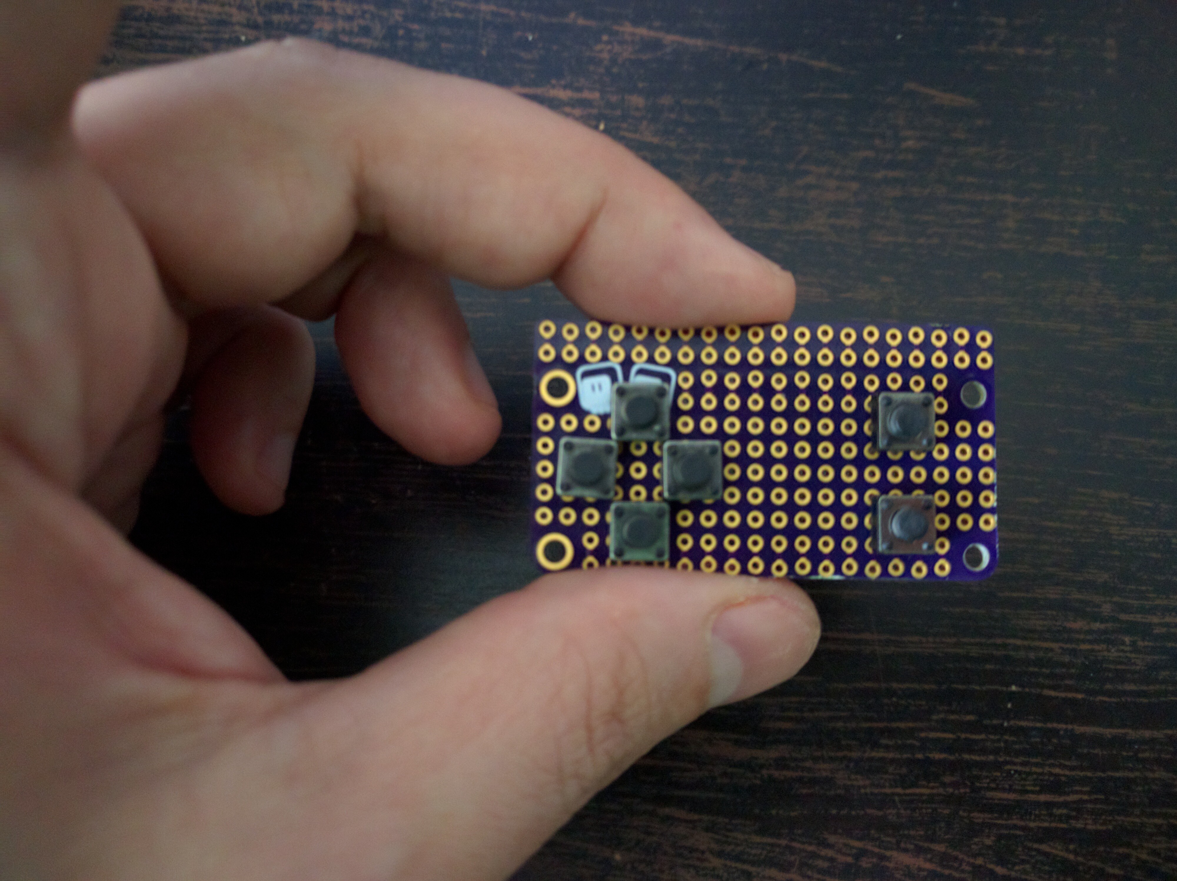
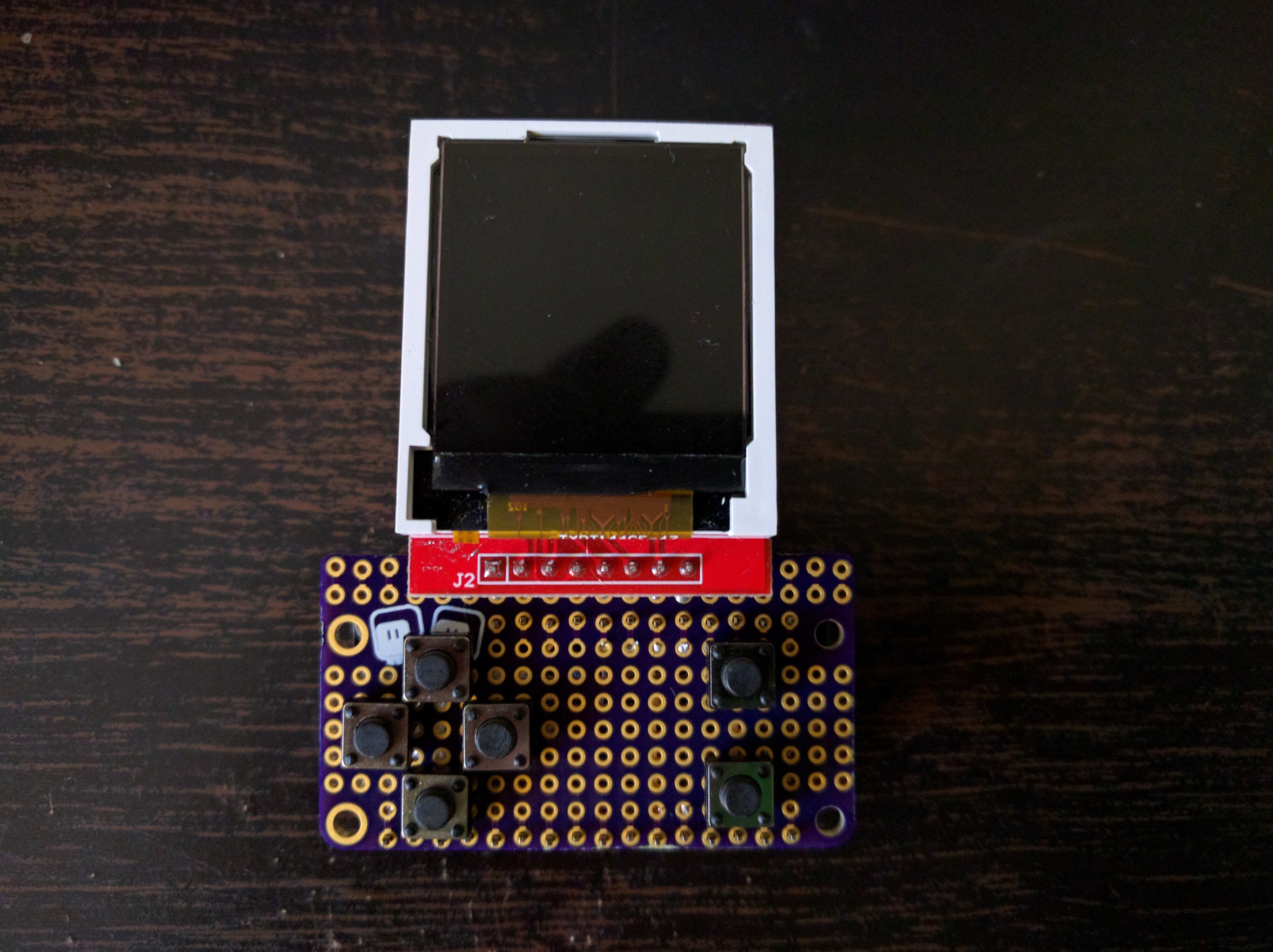
And we have out gamepad:
Next, we need to wire the display module. I used a module with the same ST7735R display as I used on the µGame, so that I can use the same code, but you can also use SSD1331, SSD1351, HX8353 or ILI9341.
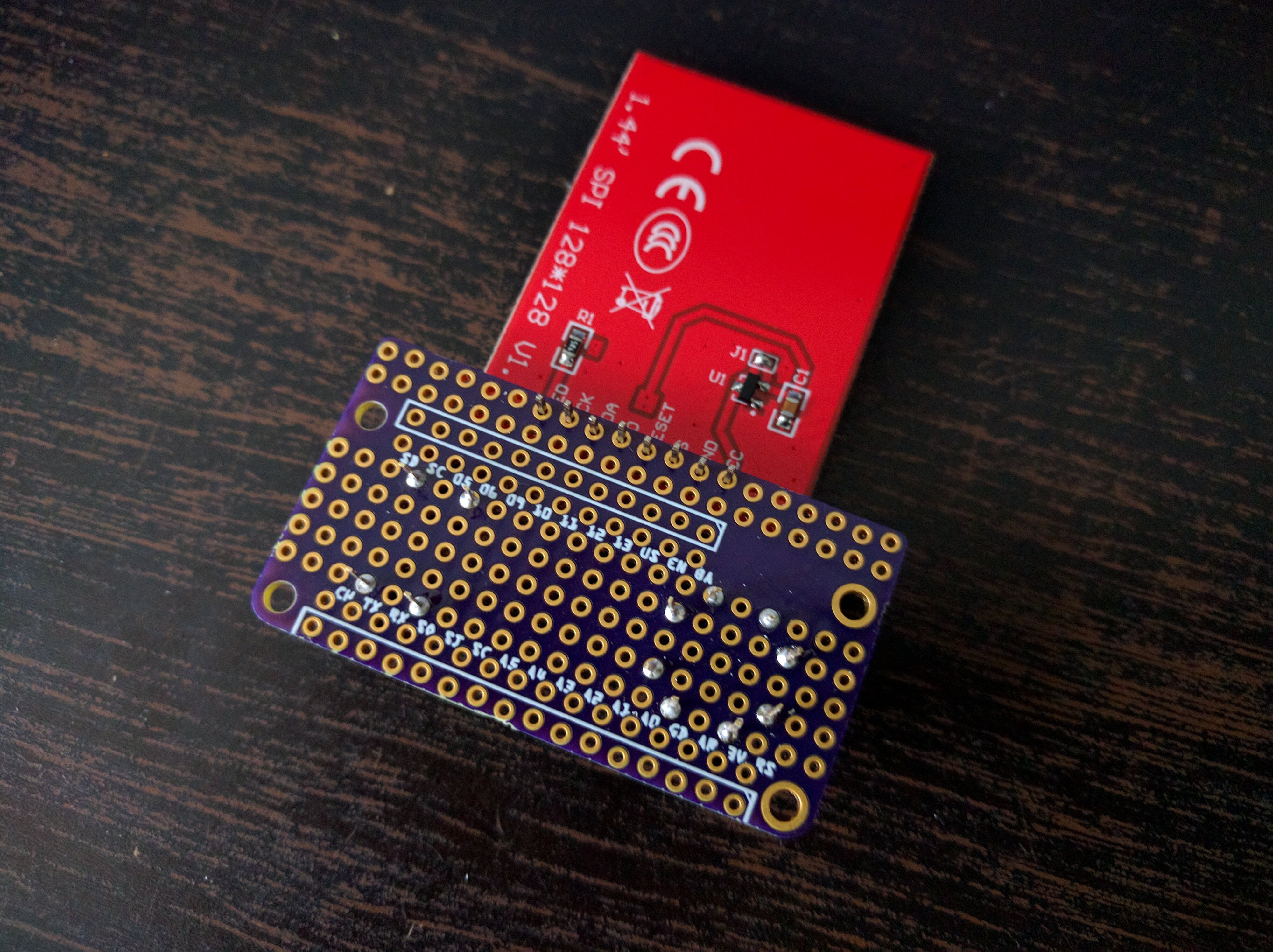
I wired it to the SPI pins of the feather, with CS pulled low permanently, RST connected to feather’s reset, and LED pulled up.
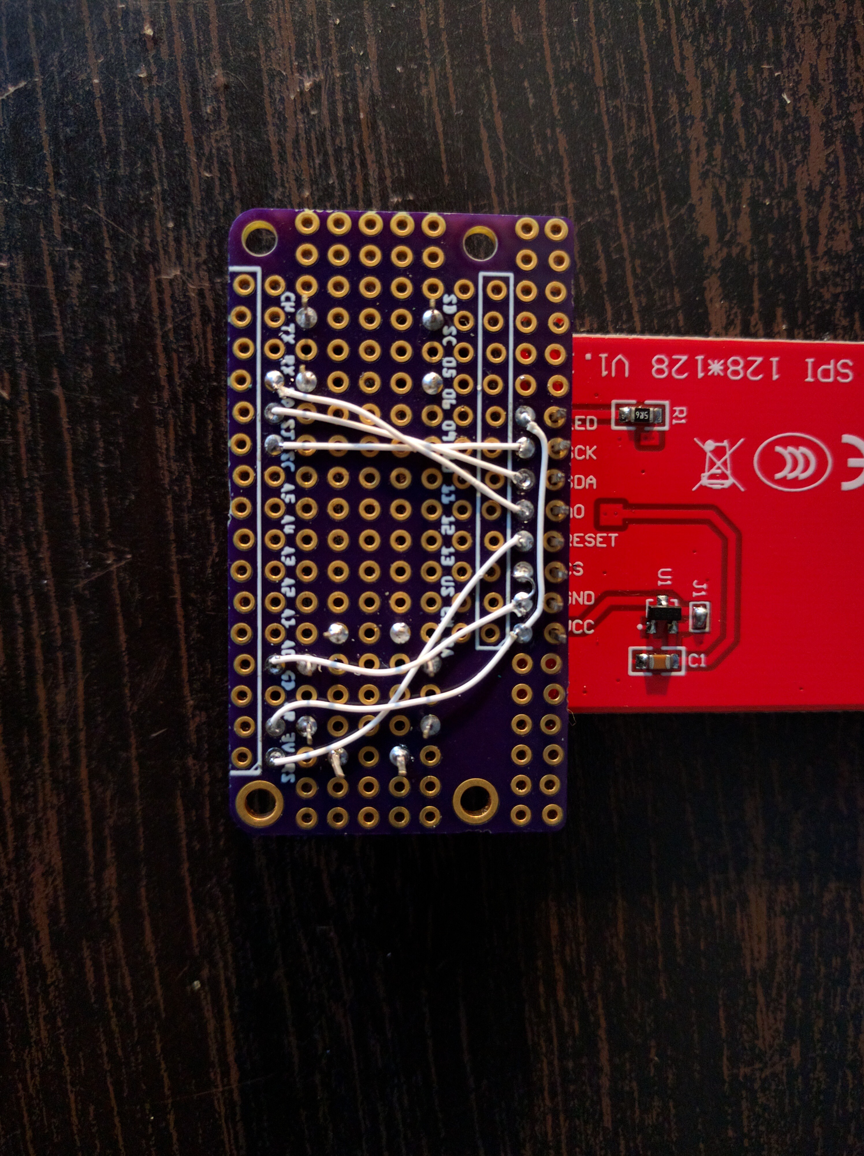
Then I also wired the buttons — one side of each button goes to GND, and the other side to one of the digital pins.
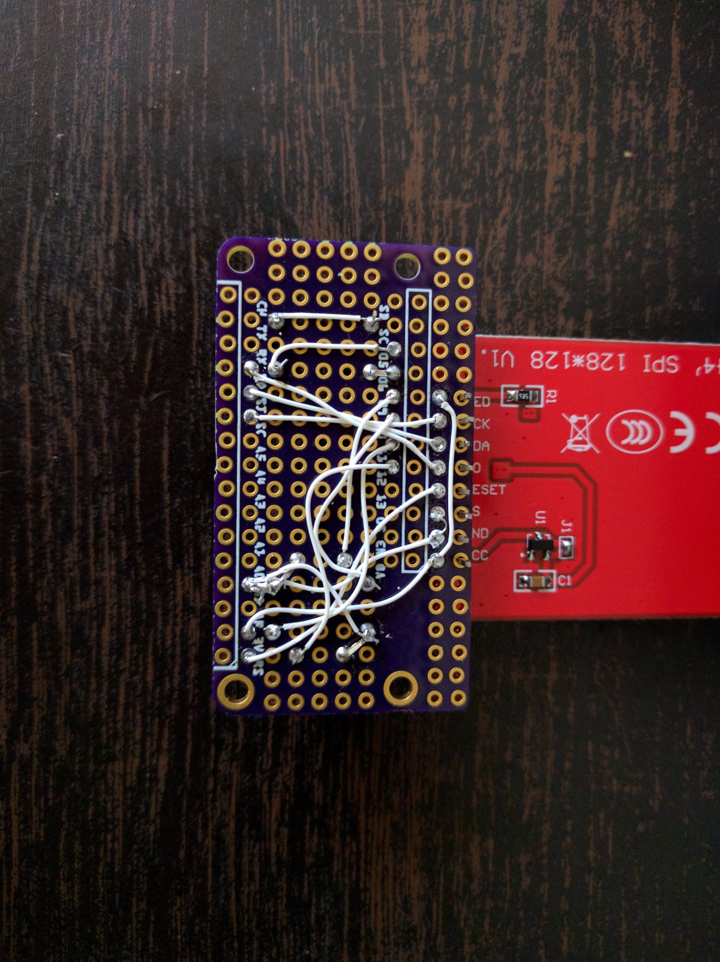
And that’s it. Add some pin headers, and plug it into the feather:
Next, I had to compile CircuitPython with my library enabled, and provide custom initialization code:
import board
import digitalio
import busio

import st7735r
import gamepad


K_X = 0x01
K_DOWN = 0x02
K_LEFT = 0x04
K_RIGHT = 0x08
K_UP = 0x10
K_O = 0x20


dc = digitalio.DigitalInOut(board.MISO)
spi = busio.SPI(clock=board.SCK, MOSI=board.MOSI)
spi.try_lock()
spi.configure(baudrate=23000000, polarity=0, phase=0)
display = st7735r.ST7735R(spi, dc, 0b110)
buttons = gamepad.GamePad(
    digitalio.DigitalInOut(board.D6),
    digitalio.DigitalInOut(board.D11),
    digitalio.DigitalInOut(board.D12),
    digitalio.DigitalInOut(board.D9),
    digitalio.DigitalInOut(board.D10),
    digitalio.DigitalInOut(board.D5),
)
(Since that module doesn’t use the MISO pin, I used it for D/C). I uploaded my work-in-progress demo game, and voila, it works!
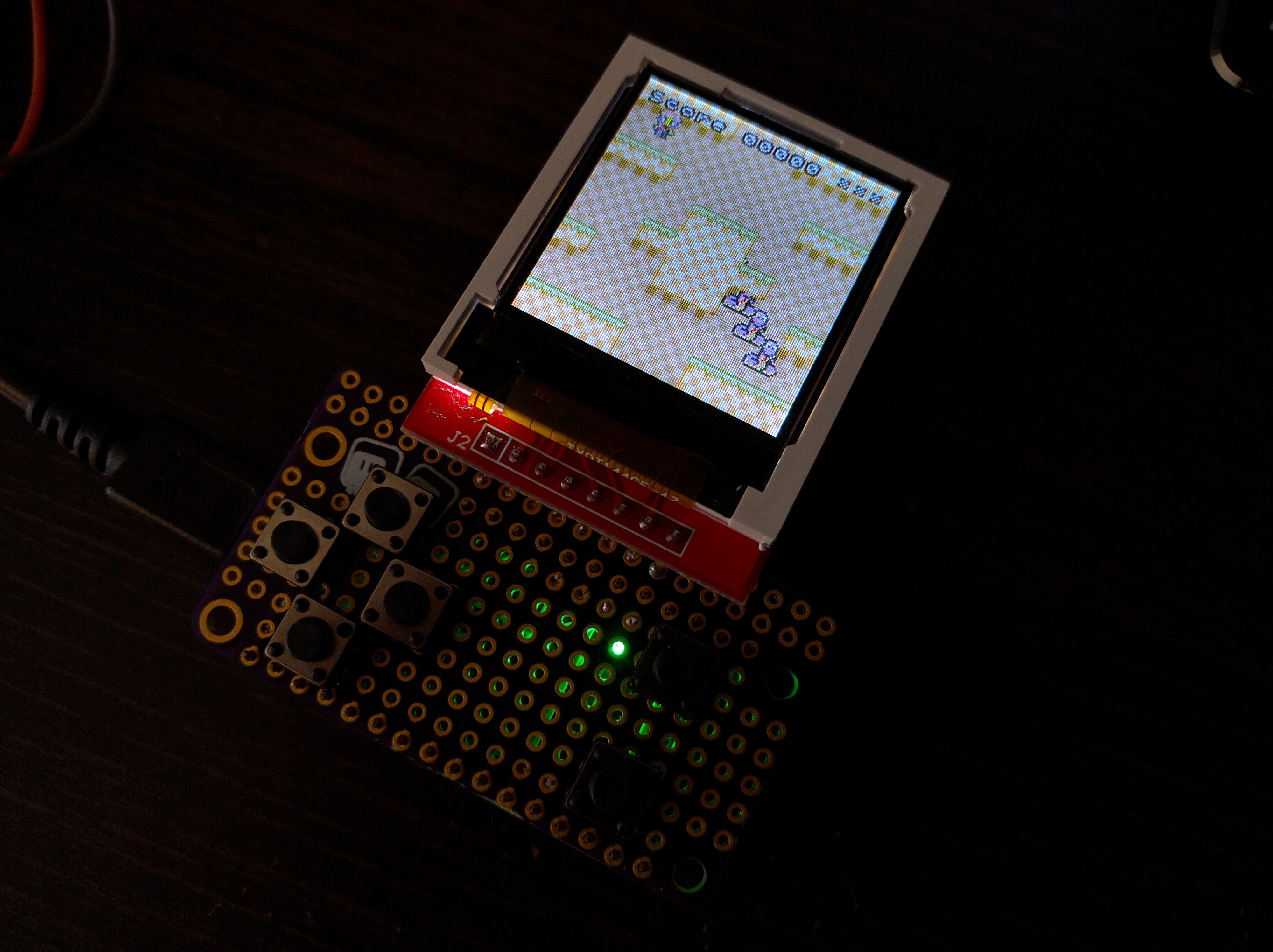
UPDATE: I had to make two changes compared to these photos. One, I forgot a wire from the fire buttons to the GND, and two, I now connected the CS pin to D13, instead of directly to GND.