Trinket M0 TFT — Mirrors, how do they work?
Published on 2017-09-12 in Trinket Shields.
The first of the PCBs I ordered for the Trinket M0 TFT just came, and I started assembling it:
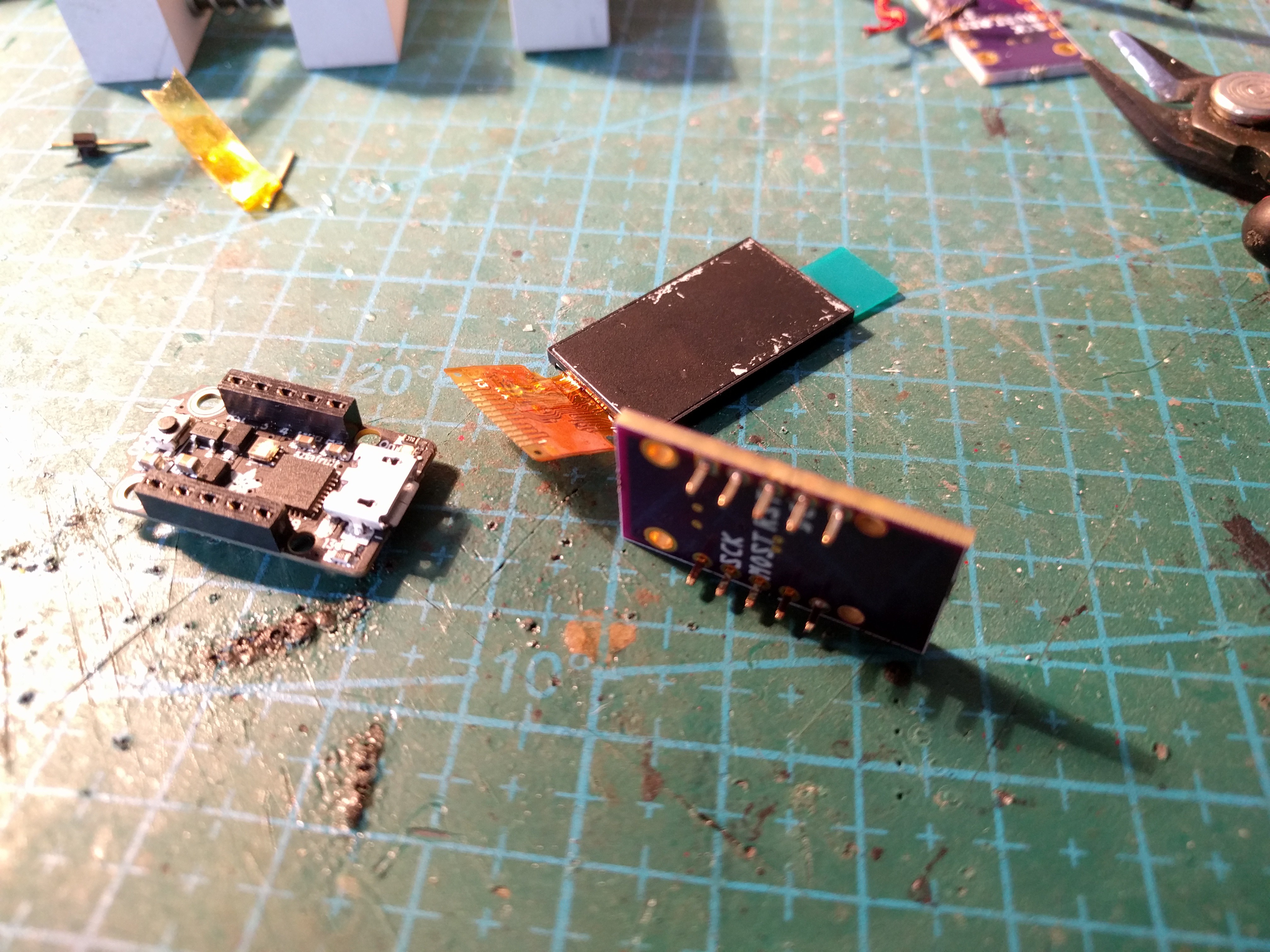
I can get a really low profile with the narrow headers and with male headers that have the plastic removed, so this is nice. There is however a slight problem. Even though the display is the only component that goes onto that PCB, I still managed to get it wrong: I used a mirrored footprint, copied from my previous design that had the connector on the underside of the board. But this board has the connector on the top, so it’s rotated 180°. And it’s too far from the other edge of the PCB for me to just rotate the whole display and use it like that.
And of course, I used the same connector design in the next two versions that I ordered, so they are also going to be wrong. So I quickly went and ordered a fixed version:

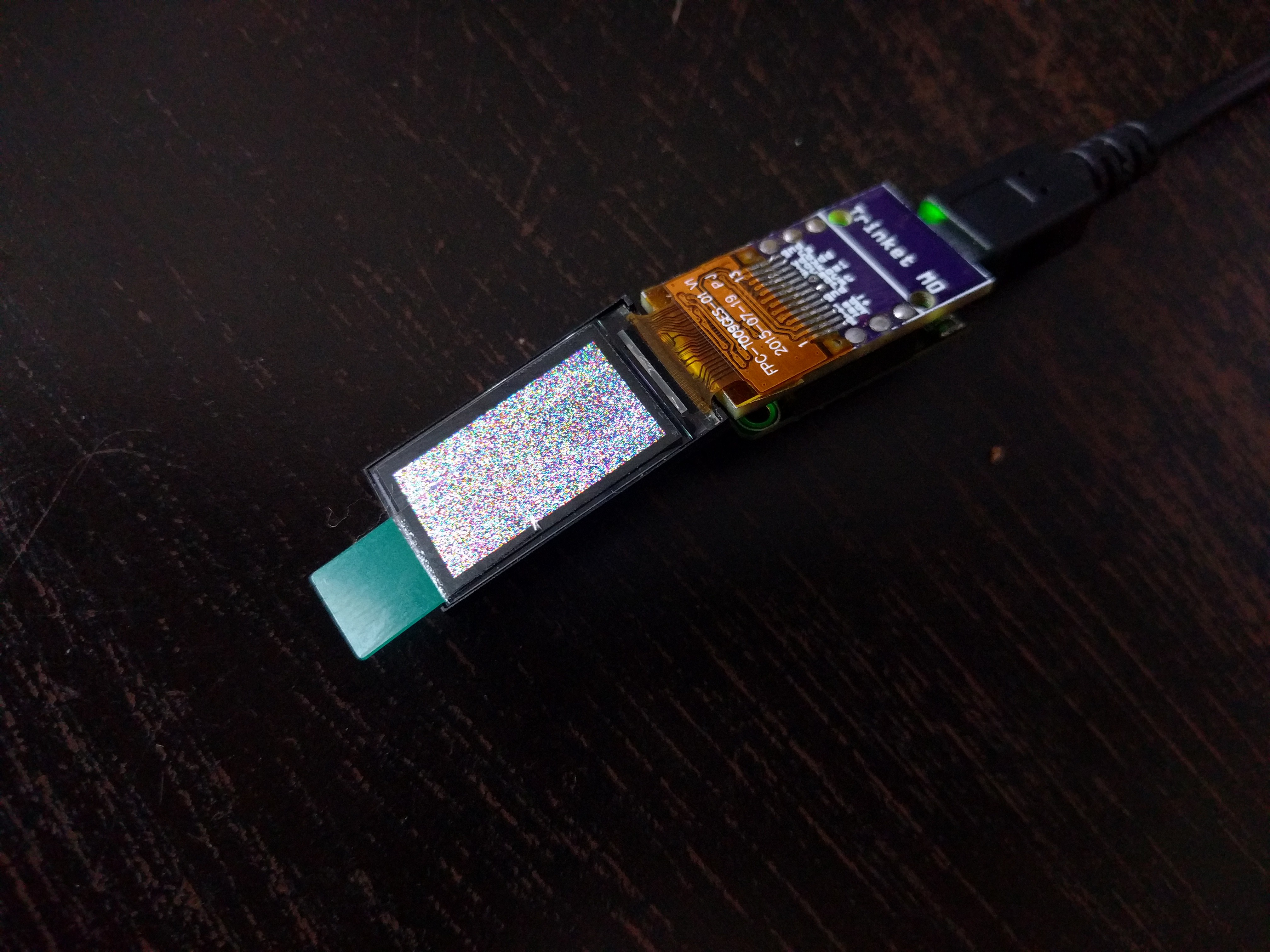
Even the routing was simpler with the mirrored display. I ordered this one with Super-Swift service, so hopefully I will have it this month. In the mean time, I still soldered one display to the board I have, to make sure there are no further surprises. It works as expected: