Some Fixes
Published on 2017-09-24 in PewPew FeatherWing.
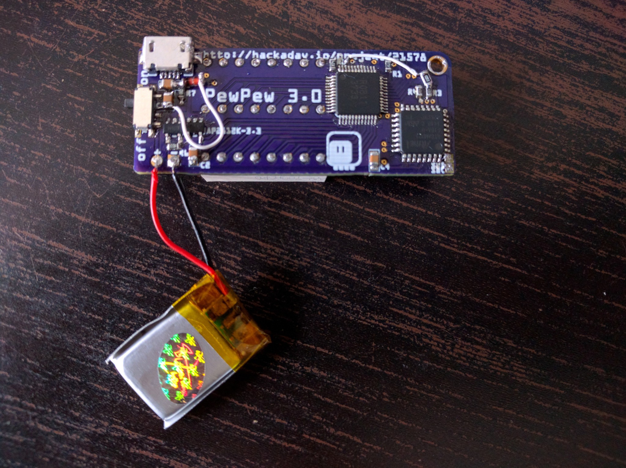
I wrote the library for the PewPew 3.0 version, and also did some more testing of the hardware, which uncovered a number of mistakes.
First of all, I forgot a pull-up resistor for the SDB pin of the IS31FL3733 that acts as enable pin — which means the display would switch off randomly. I added that with a piece of wrapping wire.\
Second, the battery circuit didn’t work, and it took me a while to realize that I forgot to connect it to the rest of the power of the device. That requires a Shottky diode, so that we don’t send power up the USB cable when it’s connected. Since I didn’t have any at hand, I ordered them, and for now used a regular rectifier diode. The voltage drop is higher, but it works fine with fully charged battery. That was another pice of wrapping wire added.
Both of those fixes are now included in the next version of the PCB.
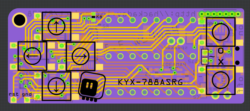
Then there are smaller issues. I realized that since this is going to be used for education, it’s likely that the device is going to be subjected to a lot of stresses. That was one of the reasons for using a LED matrix and not a glass display, for instance. But the USB port looks very vulnerable where it is, and I wanted to make sure it will be attached very firmly. So I moved the fire buttons a little bit towards the center of the board, to make room for a row of vias right under the USB socket. That should really secure it in place properly.\
Next, the SWD pads (in the lower right corner) are a little too close to each other for convenient debugging, so I moved them a little and spaced them farther apart, and also broke out GND and !RST pins on the other side of the board, so that I can get to the bootloader more conveniently.
Then I went and tried to build a custom CircuitPython firmware for this board, and it turns out that it’s relatively easy to remap the pins — so I moved the pins around a little, to free the PA02 DAC pin. Some more experimenting, and it seems I can free up enough room by removing unused modules to include the audioio module. Together with the free DAC pin that means I can have some sound.
So I moved the traces for the display to pack them a bit more densely, and sqeezed a small PAM8301 amplifier in there, and a pair of pads for soldering an SMD speaker. The end result looks something like this:
I also remembered about a recent hack with Trinket M0 that expands the available flash memory with an SPI flash chip. That would actually solve a lot of problems for me, and a quick check revealed that the pins that are being used are indeed free in my design. However, there is physically no room for a SOIC-8 chip in there.
I might actually try and go for the sandwich approach, with a second PCB acting as the back plate for the whole device — the cost of the PCB would be negligible, and I would have so much more room for everything…