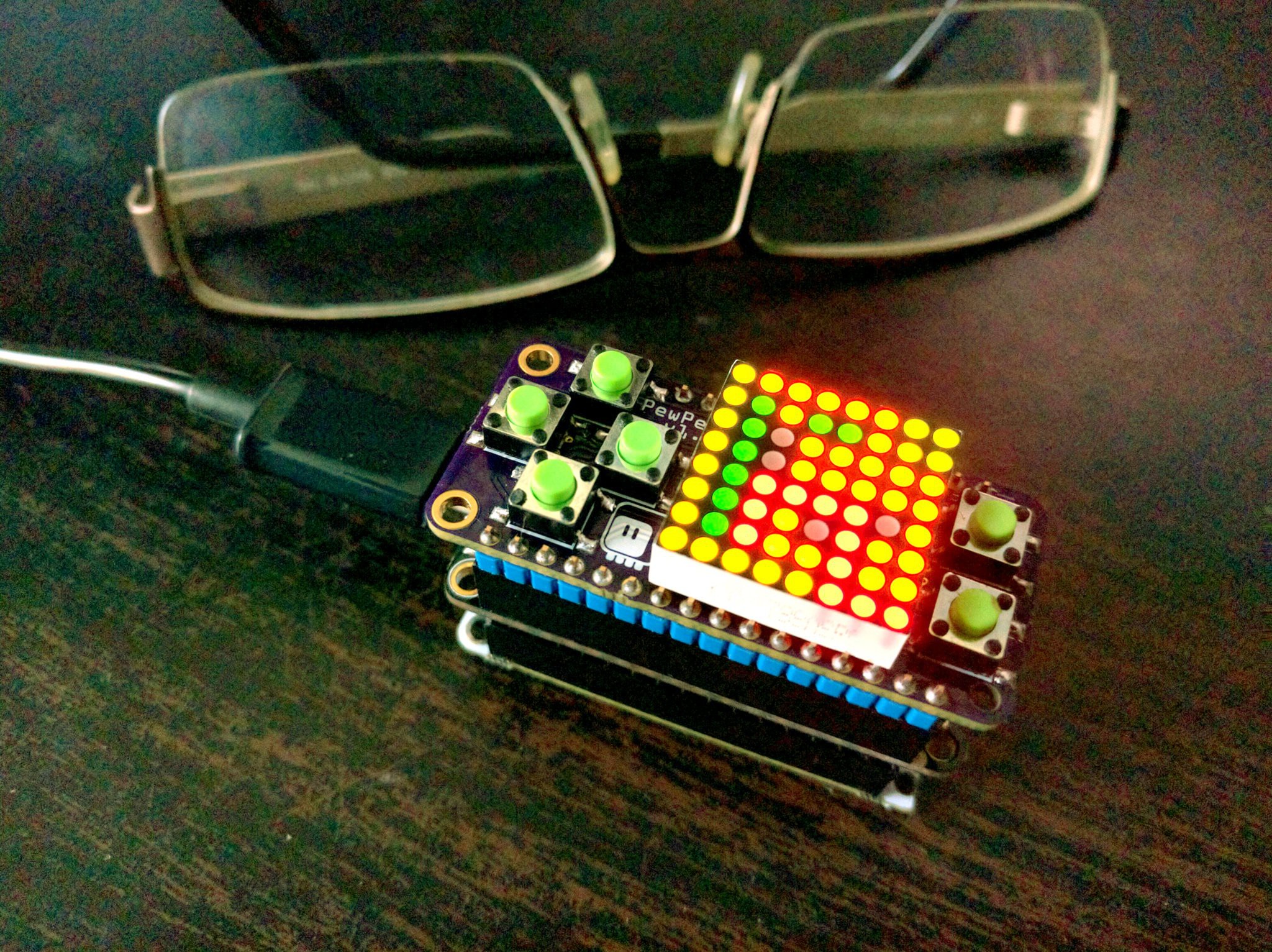
PewPew FeatherWing
A shield for Adafruit Feather boards with buttons and a LED matrix display, for simple games.
Game programming is hard. Sure, you can easily throw together something in RPGMaker, RenPy or Unity3D, and it’s great – but you don’t actually know how it works inside. There is a certain skill required to go from scratch, write your own main loop, handle events, push the pixels, etc. Incidentally, the same exact skills are required when programming any other interactive system, such as a graphical user interface, an automatic appliance, a mobile art installation or… a robot! Those are going to be much more common in our lives soon. If we want to stay in control, we need to be able to program them ourselves, and for that we need those skills. They empower us and give us back the control over the technology.\
One great tool for teaching it is PyGame – which is a library, and not a game engine, so it forces you to attend to all those pesky details of game engine internals yourself. Which is a bit difficult, of course, but ultimately very useful. But even if you play with PyGame on the Raspberry Pi, it’s still a very complicated and difficult to understand system. The learning curve is steep, and debugging is hell.
Enter MicroPython, and one of its flavors, CircuitPython. It’s written by the people at Adafruit with the education in mind, but it runs on infinitely simpler devices than your average computer. Devices which you can’t break easily, because reflashing the program will reset them to a known good state. Devices which run on batteries for hours, and which you can carry in your pocket. Devices, for which there is a plethora of add-ons and sensors that you could make use of in your game.
However, as of yet, there is no game library and/or add-on that would allow to easily create games in CircuitPython. This project is an attempt to fix this.\
Logs
2019-07-18 - Buttons
2019-07-15 - D1 Mini Shield
2018-10-23 - Replaced by PewPew Standalone
2018-07-14 - Making it Cheaper Again
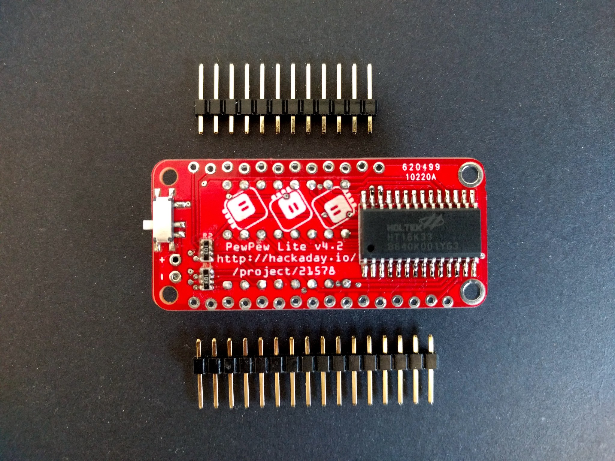
2018-05-08 - PewPew Lite Version 4.2
2018-04-18 - Version 5.1
2018-02-23 - LAMEBOY Playing PewPew Games
2017-12-06 - The Aisler Saga, Part 2
2017-11-02 - Sanity Check
2017-10-24 - Version 4.2
2017-10-22 - PyWeek Failure
2017-10-15 - PyWeek, Here I Come
2017-10-15 - PewPew 4.1
2017-10-14 - Boards from Aisler
2017-10-13 - Contest Video
2017-10-03 - Struggling with BOM
2017-10-03 - GamePad module and Trinket M0 Haxpress
2017-10-02 - Replicating the Trinket M0 Express Hack
2017-09-29 - Custom CircuitPython
2017-09-26 - License
2017-09-24 - Some Fixes
2017-09-23 - PewPew 3.0 Standalone
2017-09-17 - Tetris
2017-09-15 - Homebrew Trinket M0
2017-09-11 - Maker Faire Zürich
2017-09-07 - The Store is Live
2017-09-07 - More Quality Control
2017-09-06 - First Production Boards
2017-08-30 - Documentation
2017-08-29 - Quality Control
2017-08-15 - Final version for the PewPew Lite
2017-08-10 - Displays Are Hard
2017-08-07 - PewPew Lite Version 4.0
2017-08-06 - Why not Raspberry Pi?
2017-08-06 - The Library
2017-08-05 - Thinking about PewPew 2
2017-07-25 - Prototypes
2017-07-24 - BOM Updated for PewPew Lite
2017-07-23 - Scrolling and Text
2017-07-23 - Business Plan
2017-07-21 - The Challenge
2017-07-19 - First CircuitPython Program
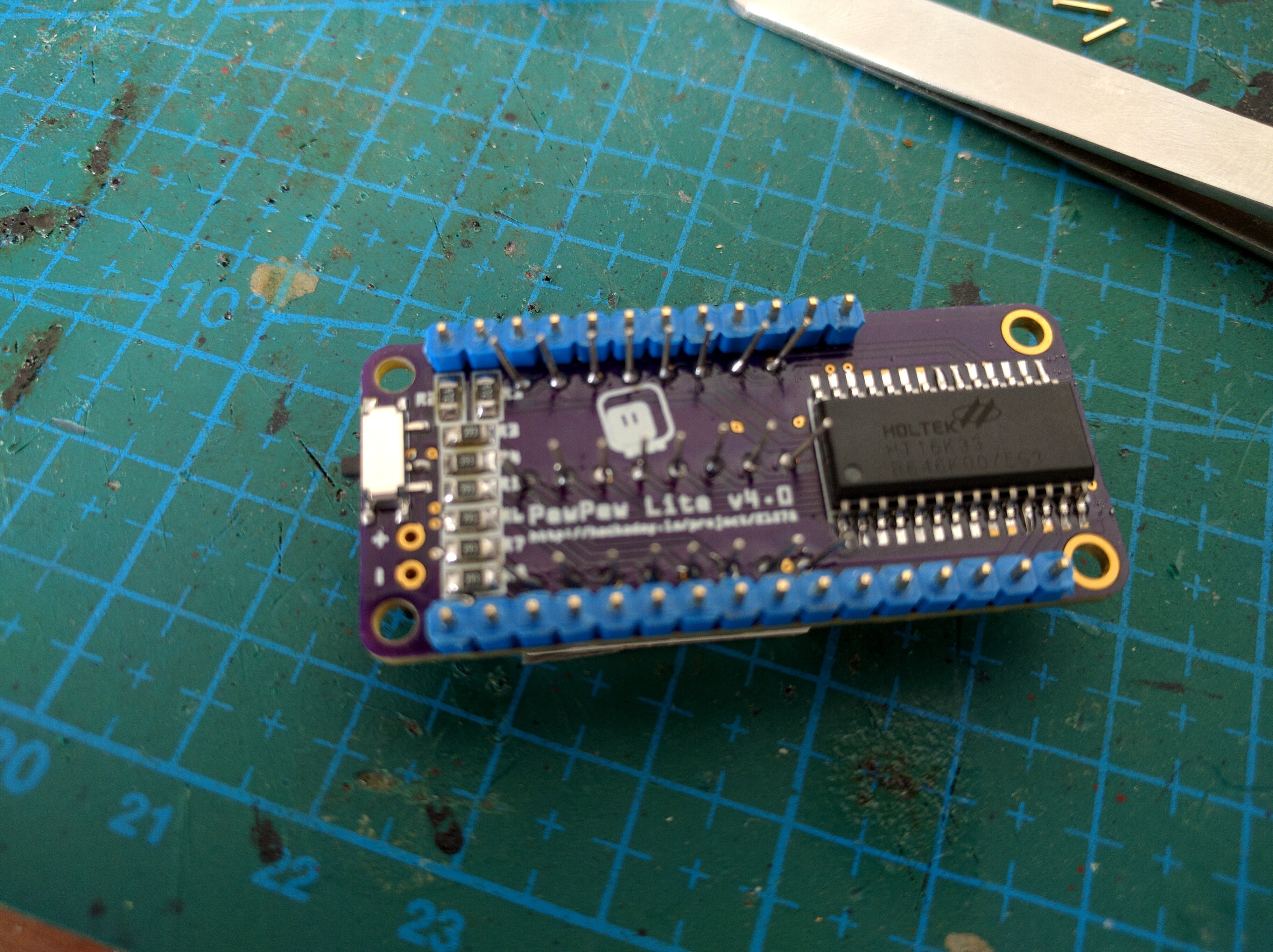
2017-07-17 - PewPew Lite Assembled
2017-07-05 - PewPew Lite Schematic
2017-07-03 - PewPew Lite
2017-06-18 - Version 1.5
2017-05-31 - Sound
2017-05-16 - ESP8266 GPIOs Suck
2017-05-13 - Version 1.4
2017-05-10 - Prototyping
2017-05-01 - The Display
2017-05-01 - The Concept
2017-05-01 - The Buttons
2017-05-01 - Ghosting
Links
Components
Component |
Count |
Notes |
|---|---|---|
PCB |
1 |
|
HT16K33 28SOP |
1 |
|
Tact switch 6x6x4.5mm |
6 |
|
1.9mm Bi-Color 8x8 LED Matrix, with common cathode (788AHG) |
1 |
|
SMD 0603 Resistor 39kΩ |
6 |
|
SMD 0603 Resistor 4.7kΩ |
2 |
|
SPDT slide switch MK12C02 |
1 |
|
2.54mm male pin header |
1 |
Instructions
Trim the matrix
Use wire cutters to cut off the excess pins, as flat against the board as possible.
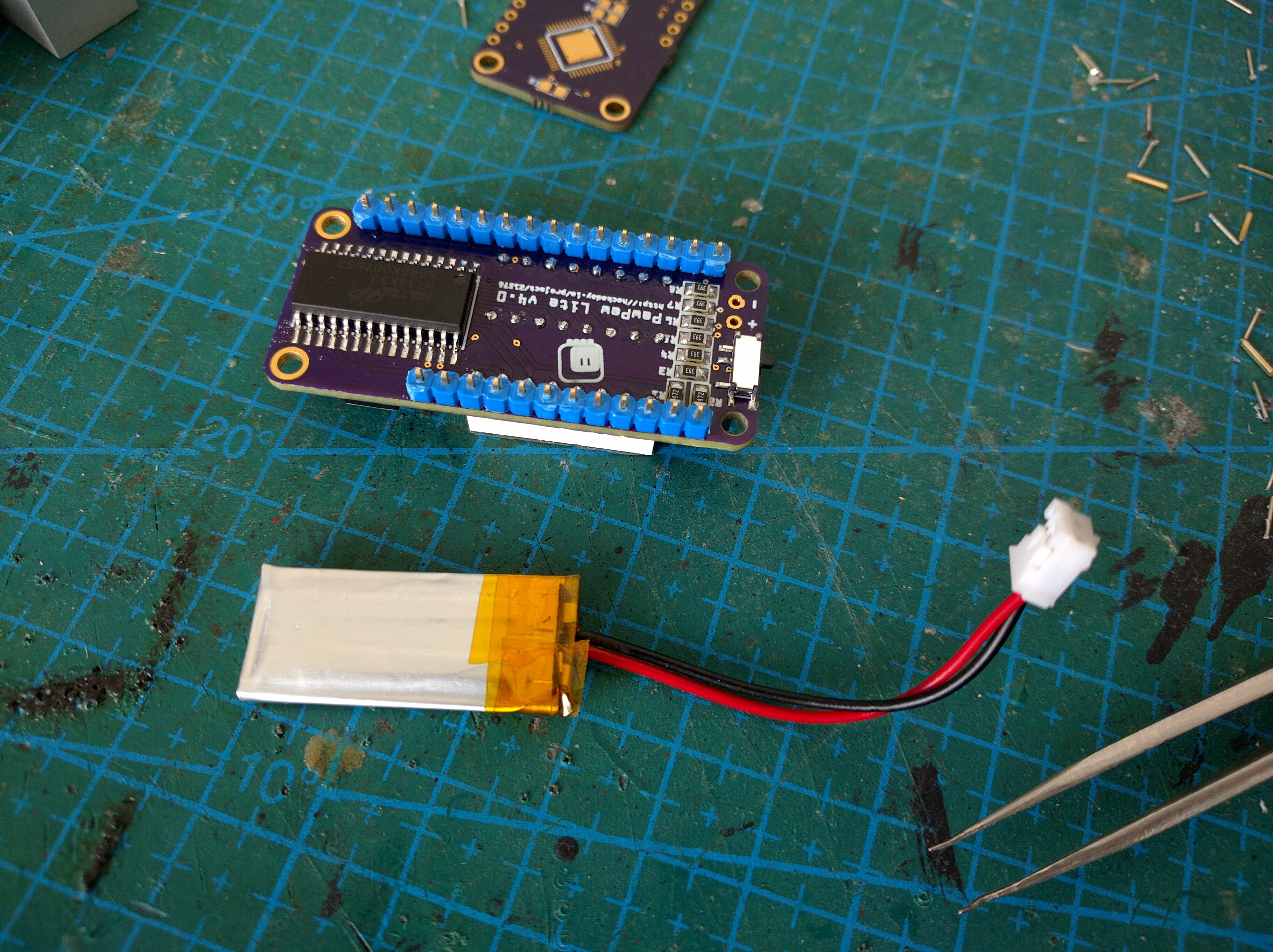
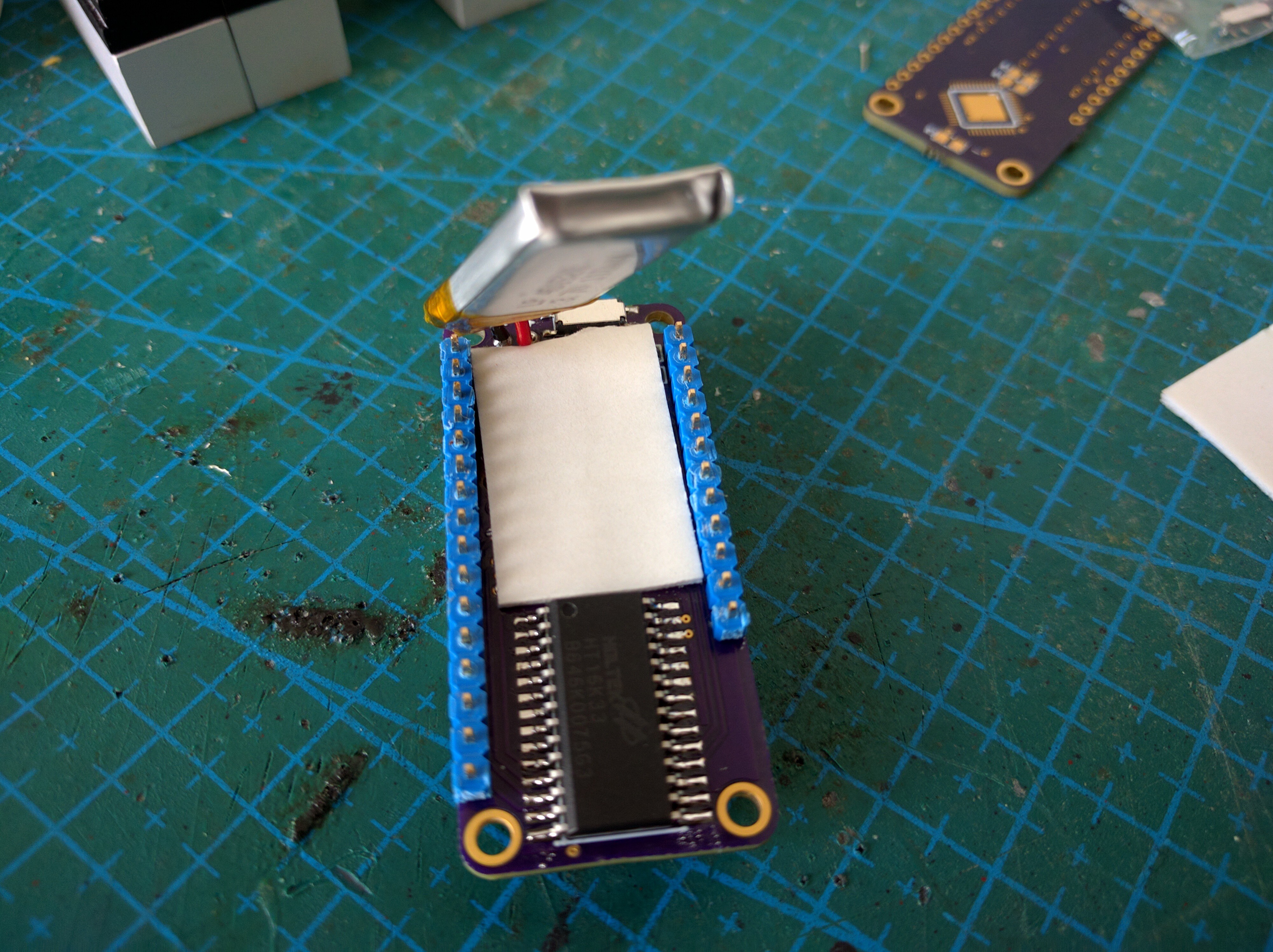
Add a battery (optional)
If you have a small battery (I used 110mAh), you can add it on the back of the board.
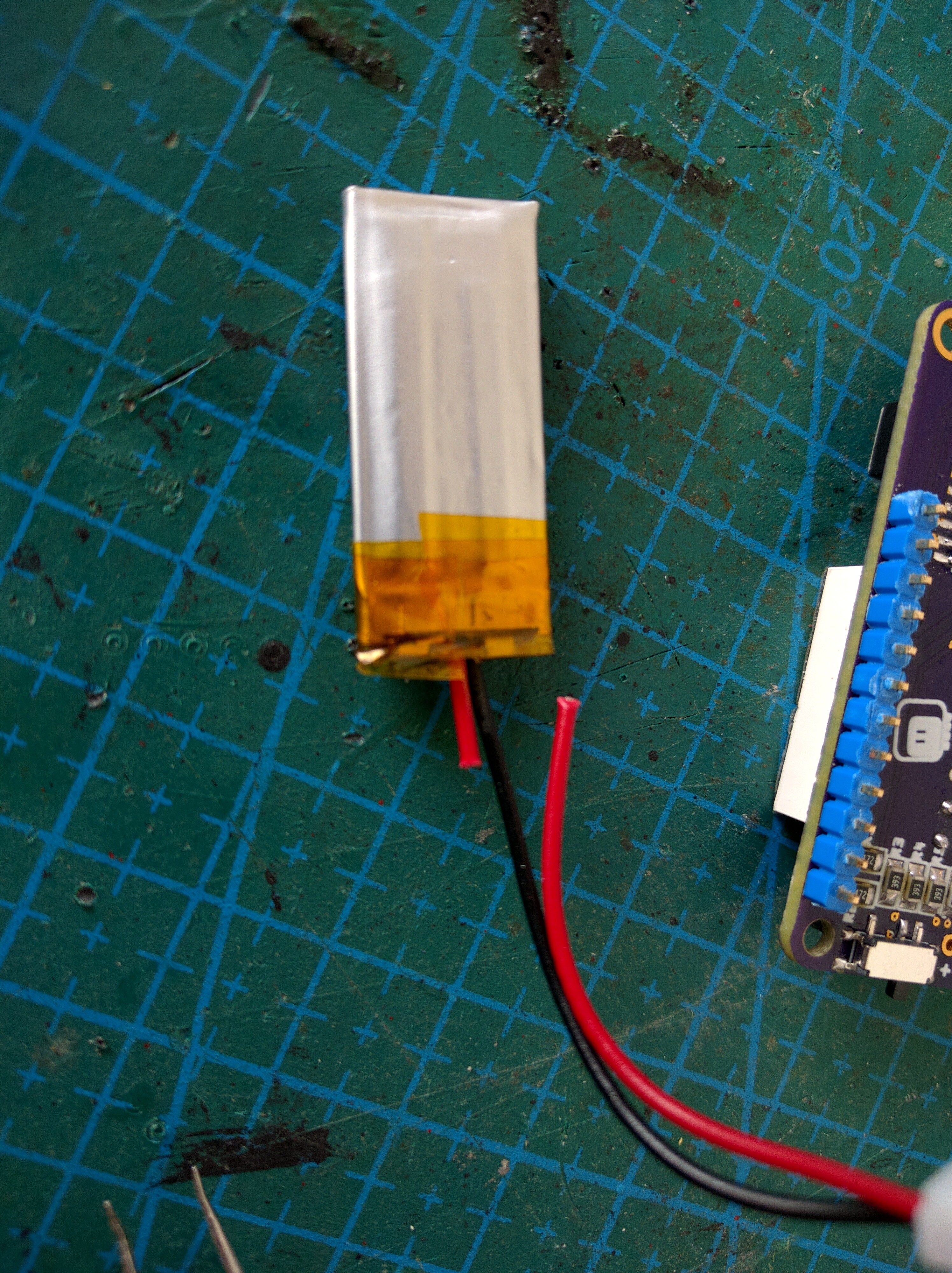
Cut the wires
Cut the battery wires to about 0.5cm. Be careful to cut them one at a time, otherwise your cutters will short the battery and make sparks fly.
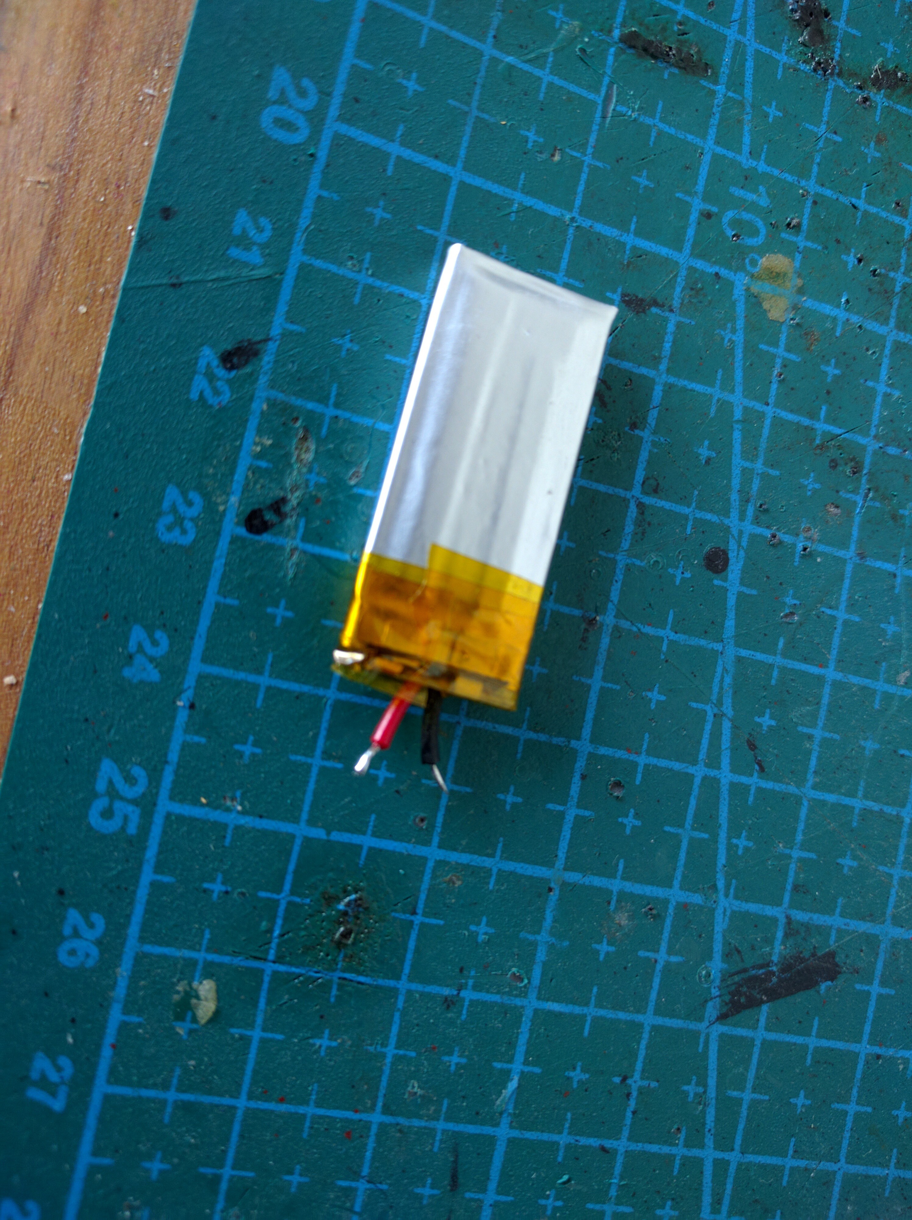
Prepare wires
Carefully remove the insulation and tin the ends of the wires. Be careful to not short them.
Solder battery
Solder the wires to the holes marked + (red wire) and - (black wire).
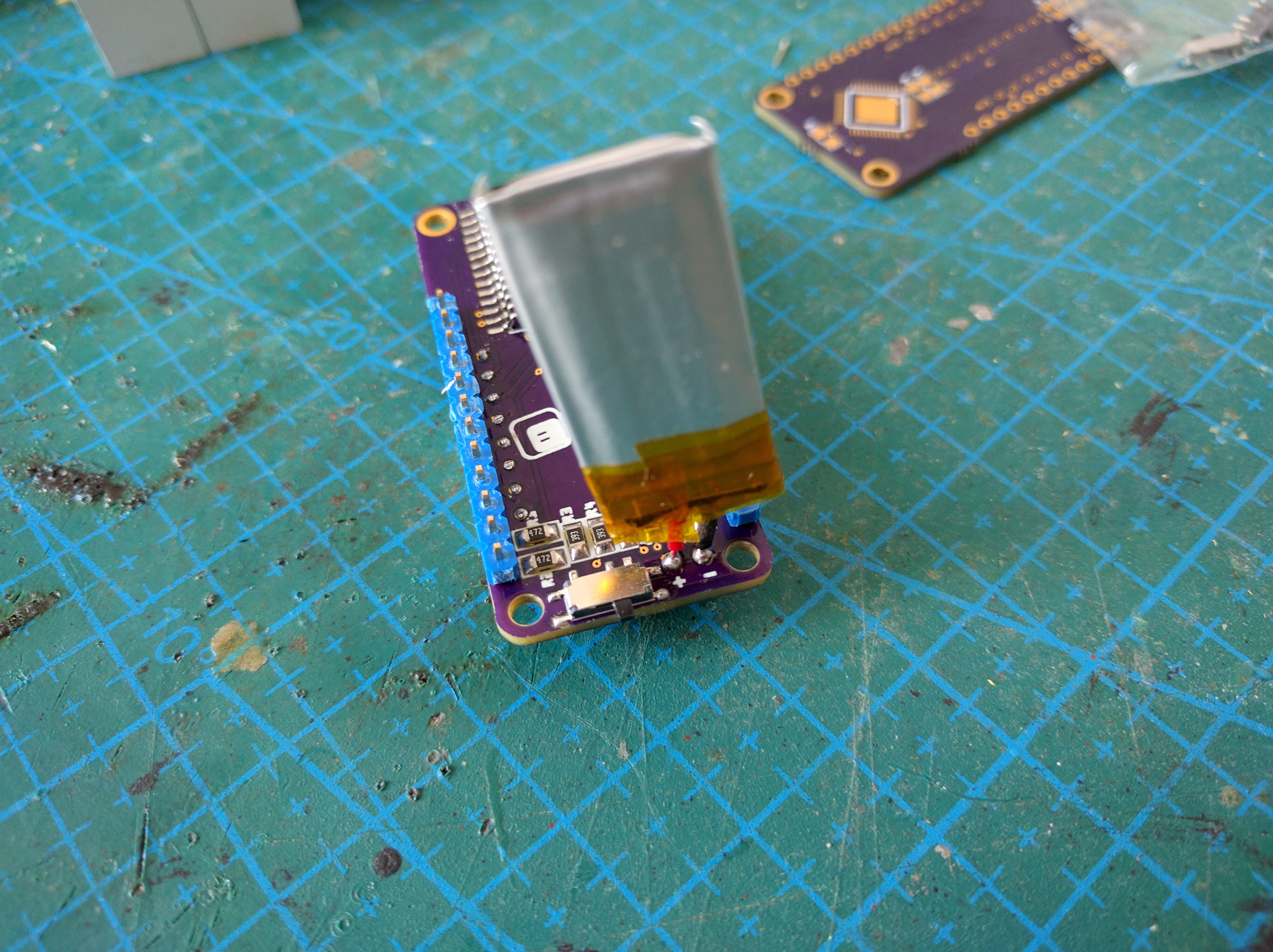
Add tape
Use a piece of two-sided tape to hold the battery in place, to prevent it from shorting the matrix pins, and to protect it from being damaged by the sharp pin leftovers sticking from the board.
More tape
Also add some tape on top, to prevent shorts on the Feather side.
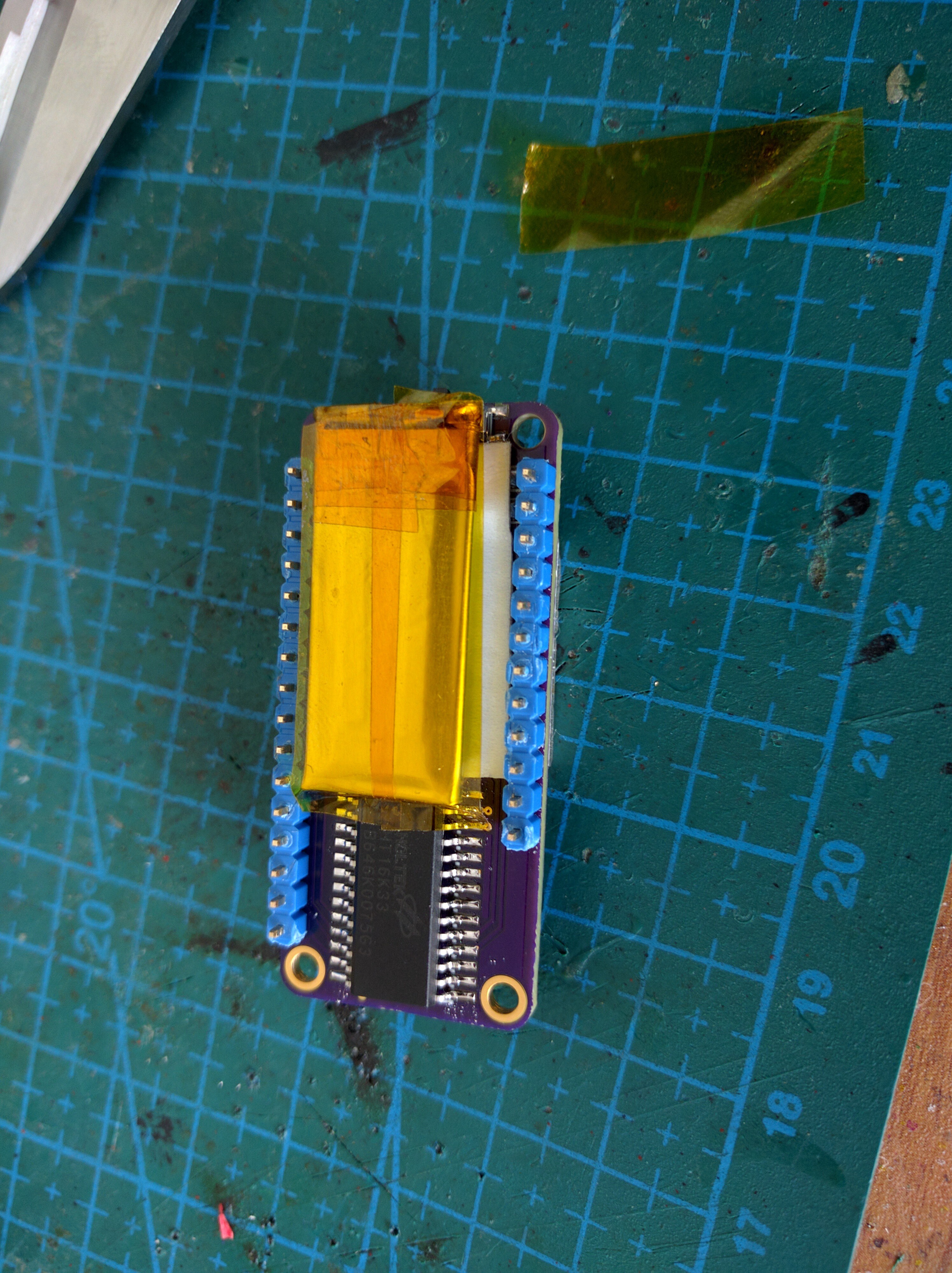
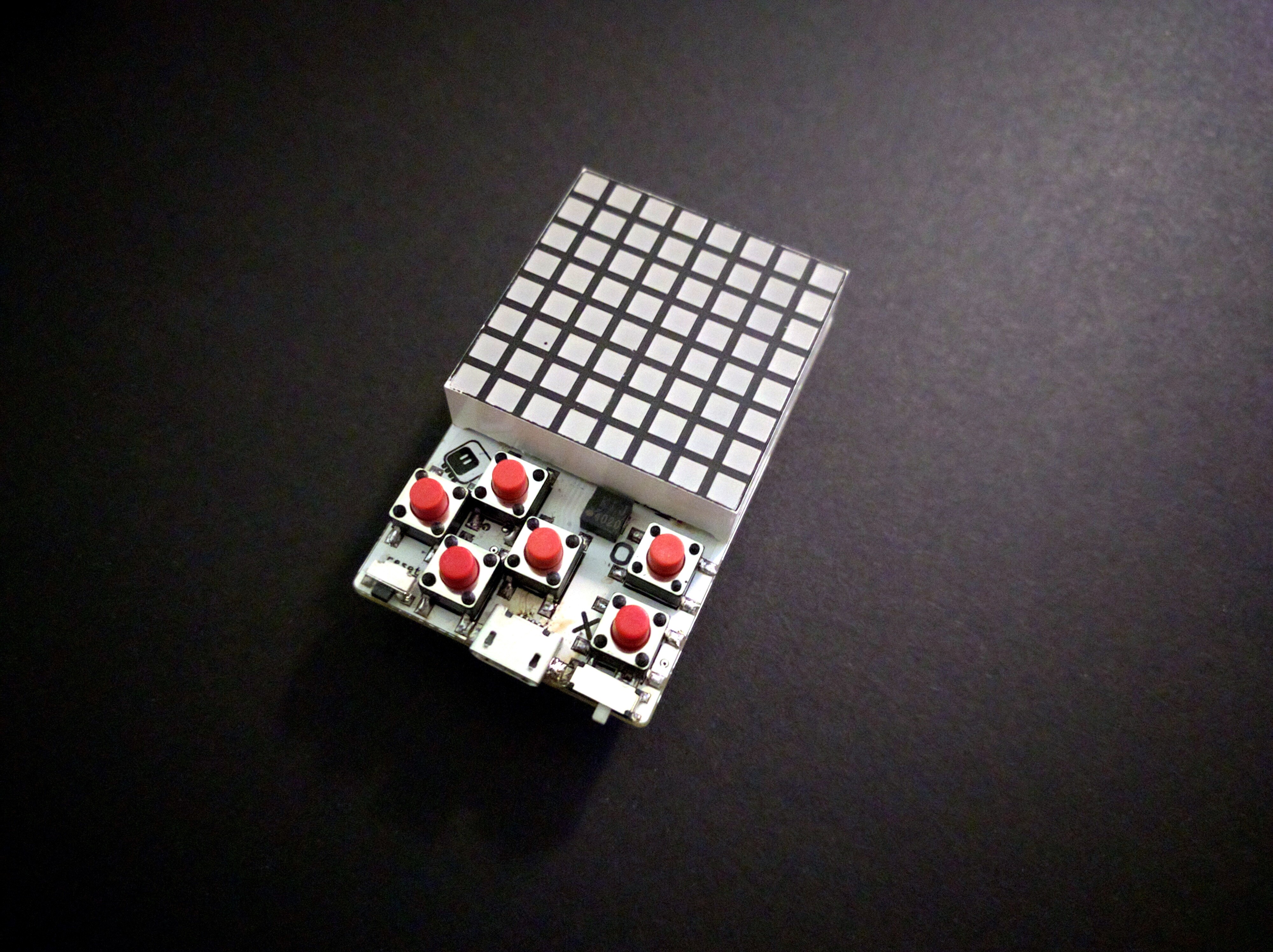
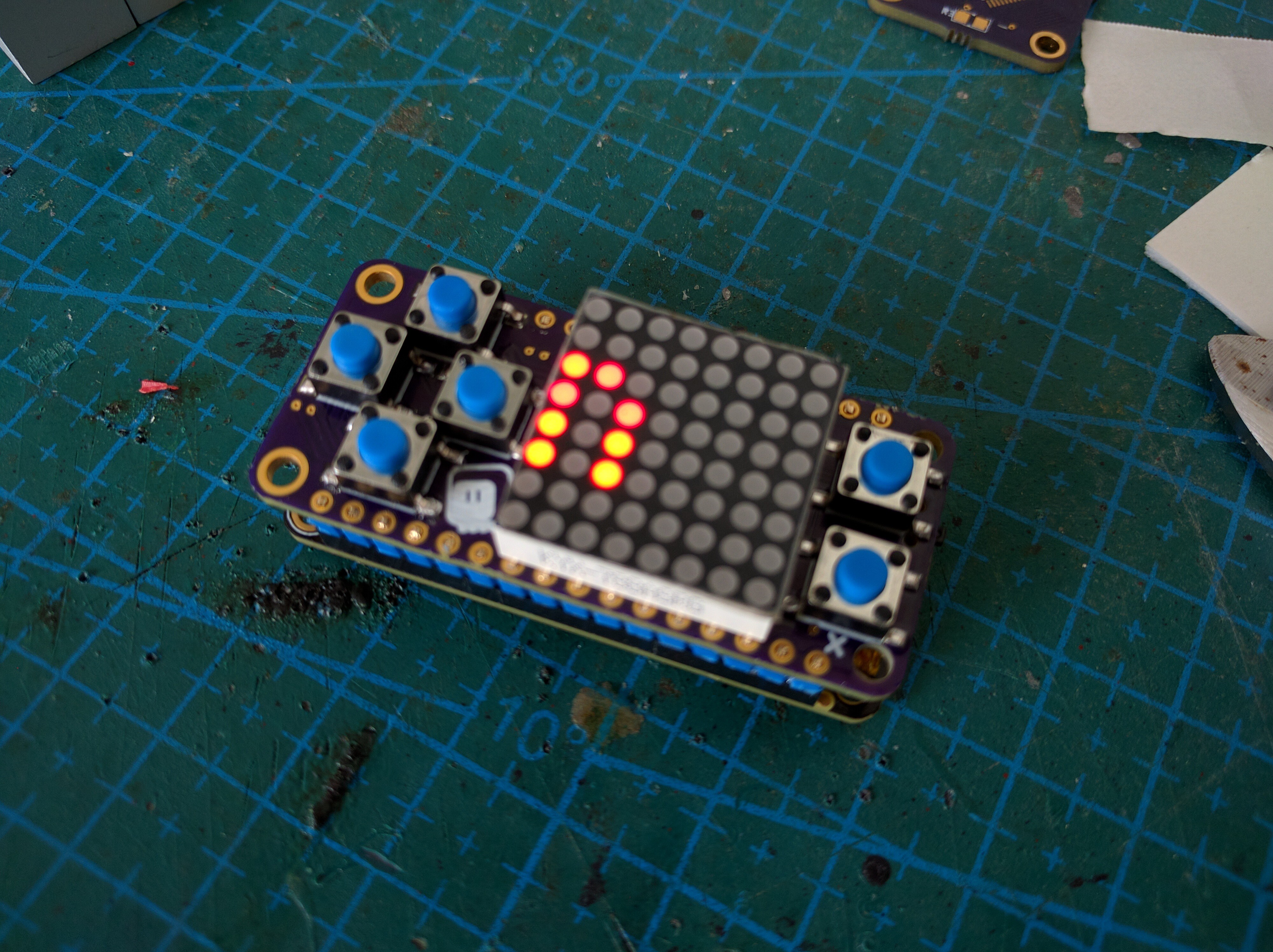
Finished
The board is finished and ready to be programmed.
Solder paste for the buttons
Heat the board a little bit with your hot-air station, and then apply the soldering paste on all the button pads.\
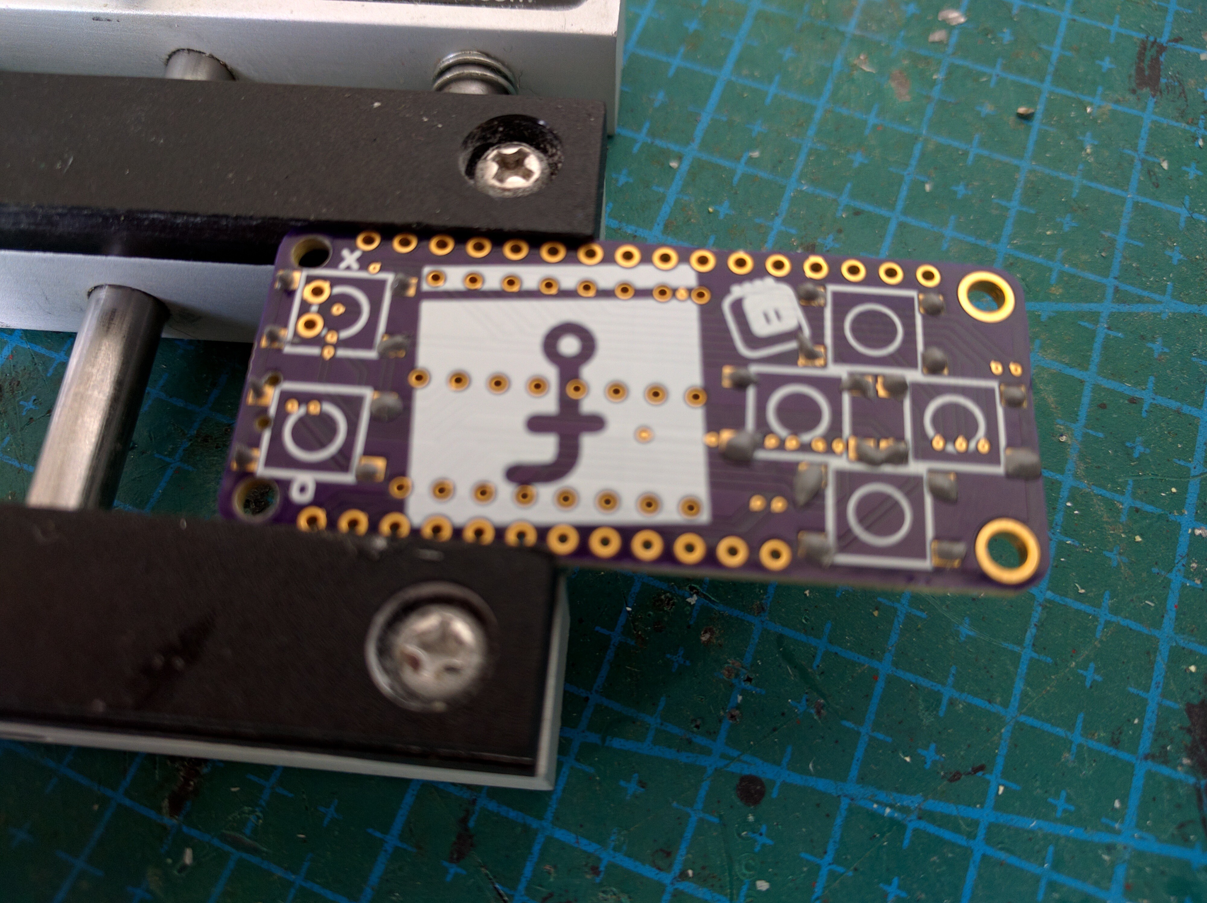
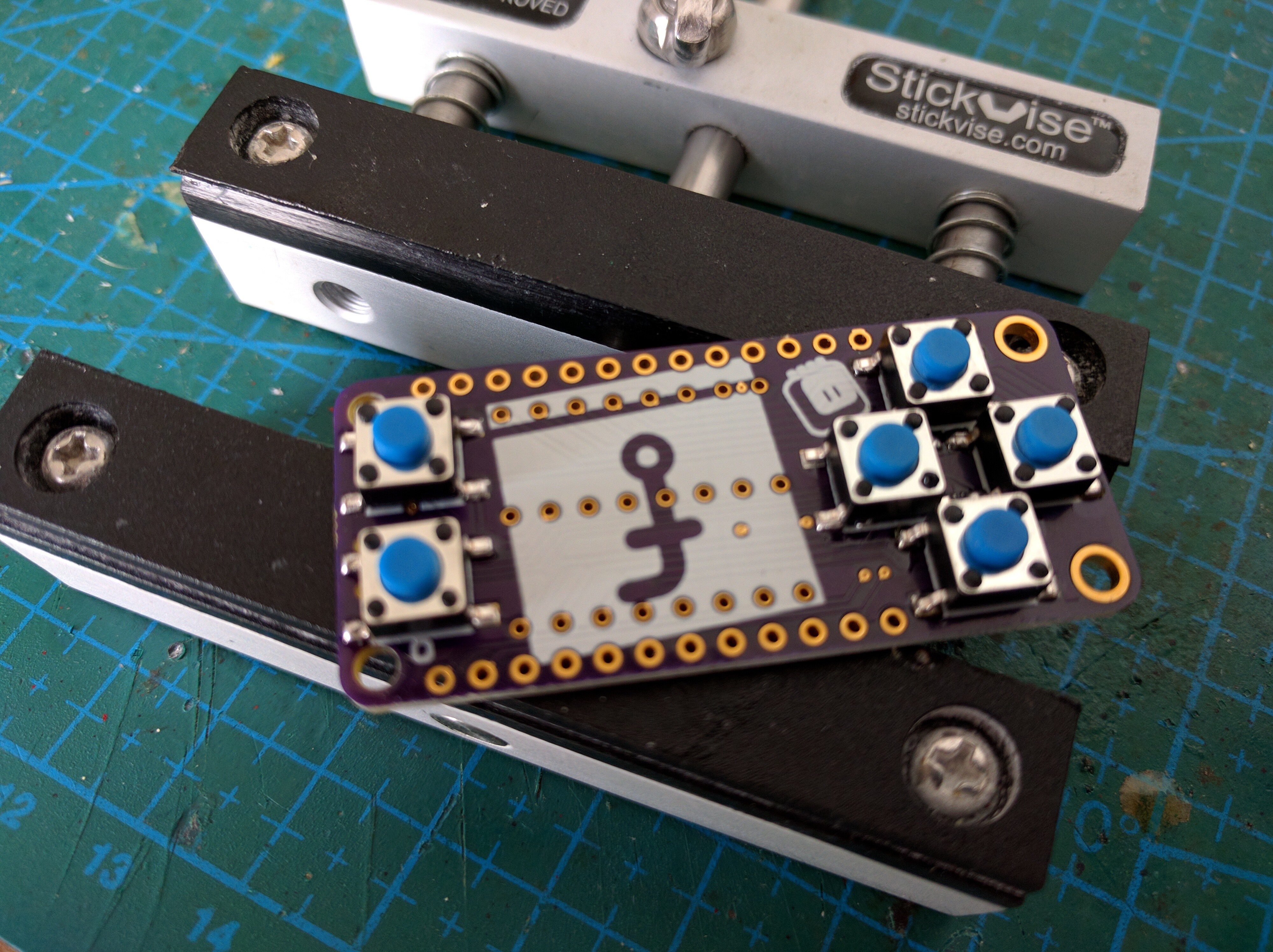
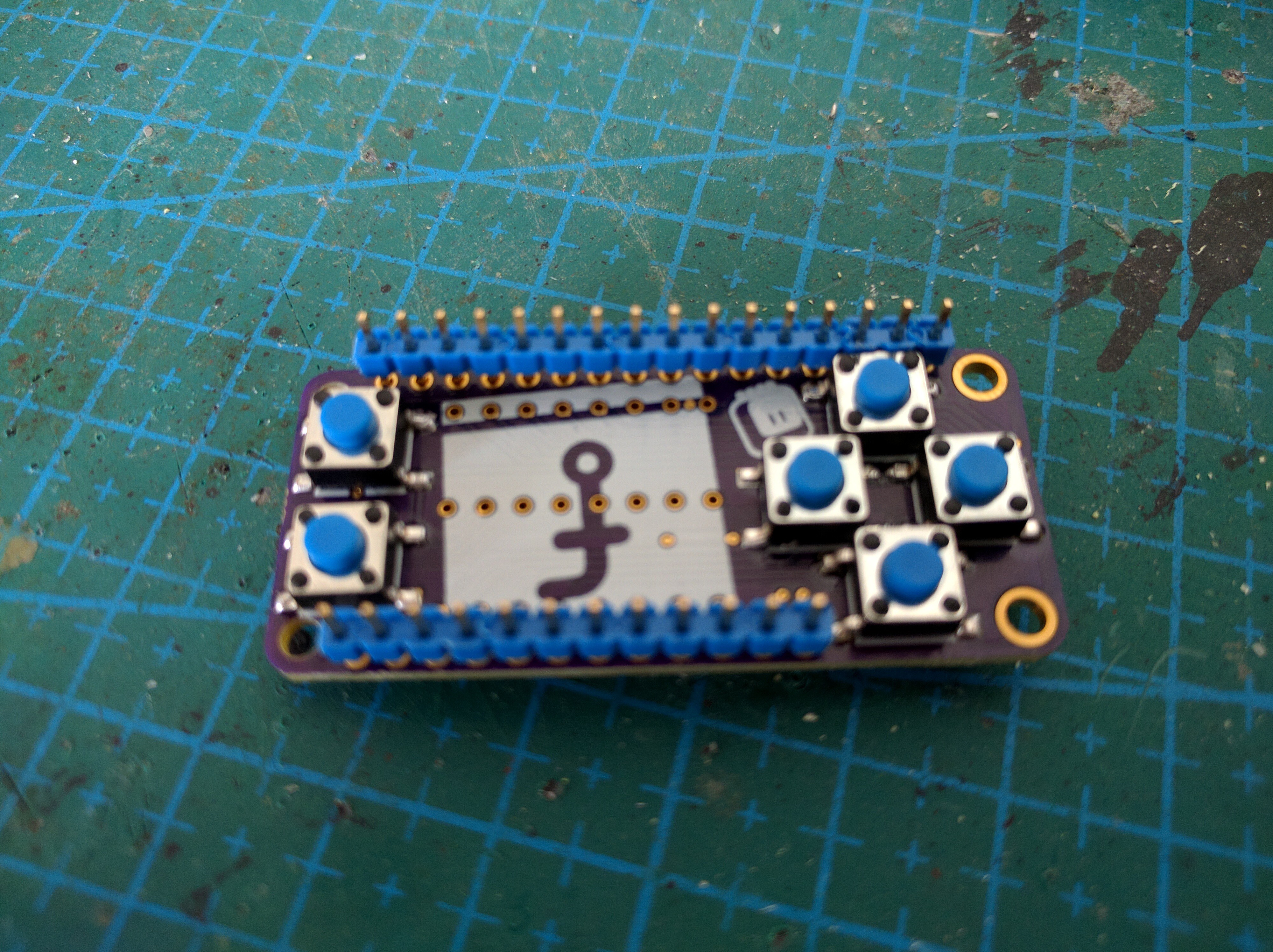
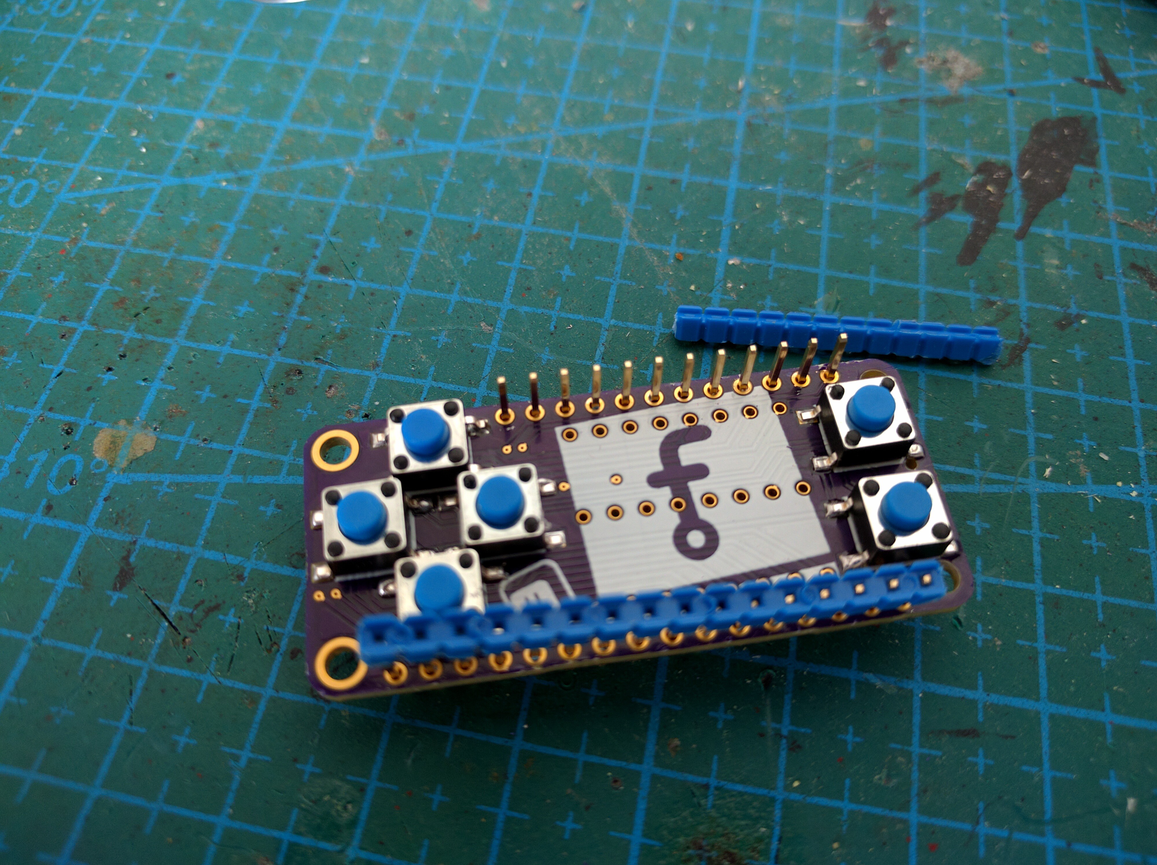
Place buttons
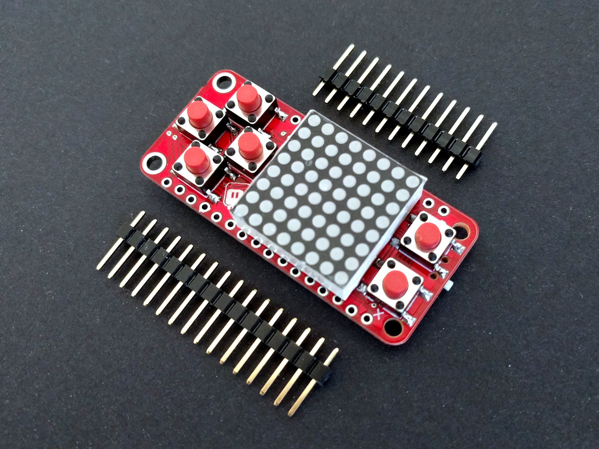
Place the buttons in they correct positions. Be careful to align them properly, as the surface tension of the solder will not be enough to move them.
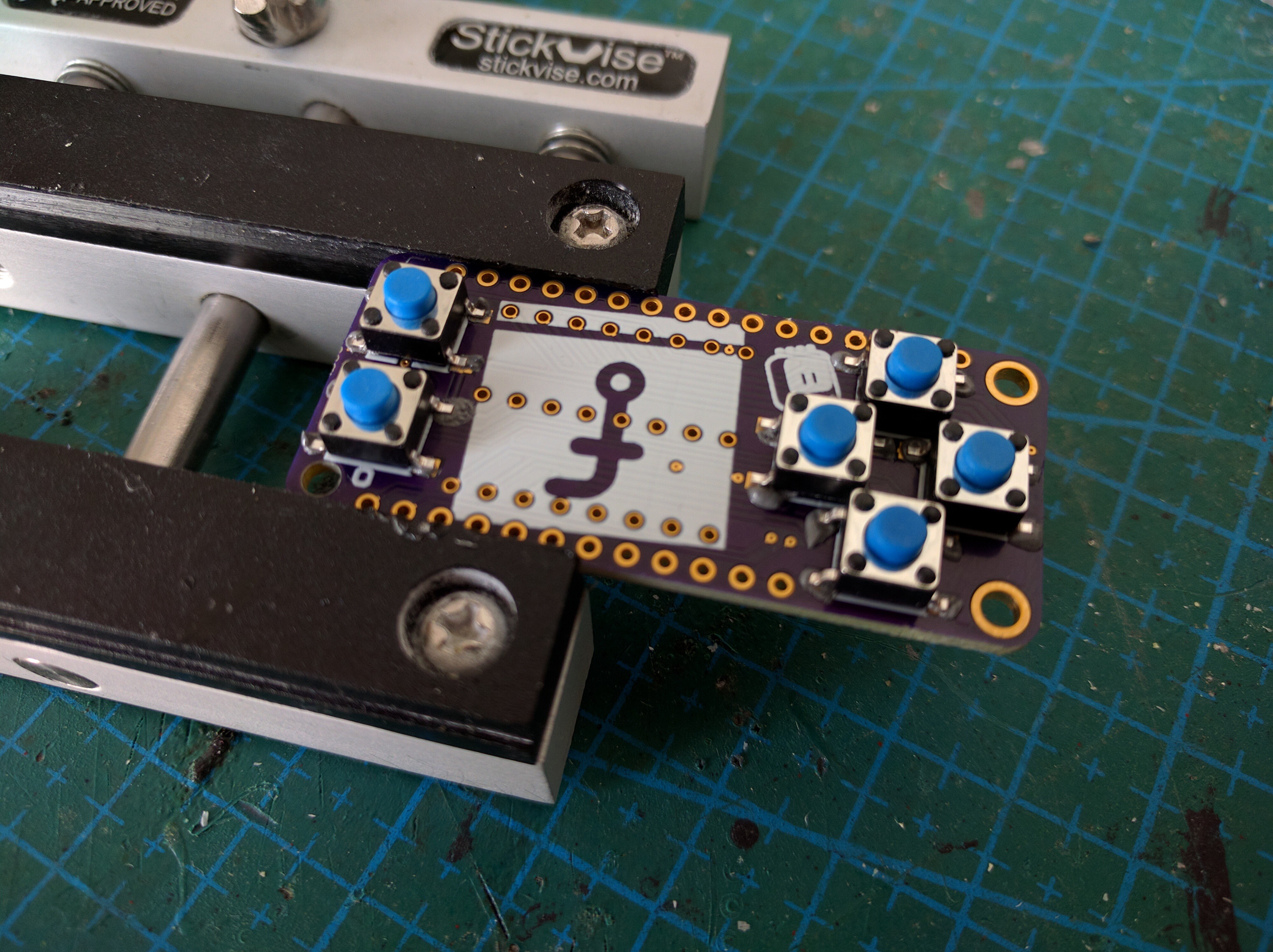
Solder buttons
Apply the hot air to solder the buttons. Be careful to not melt the plastic caps.
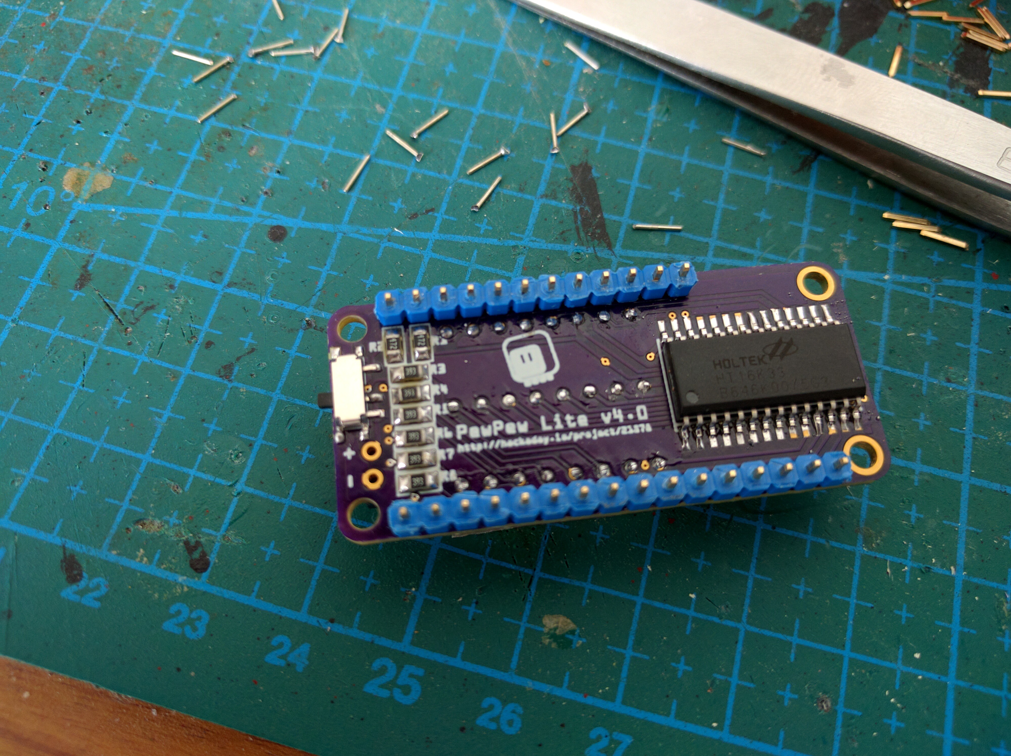
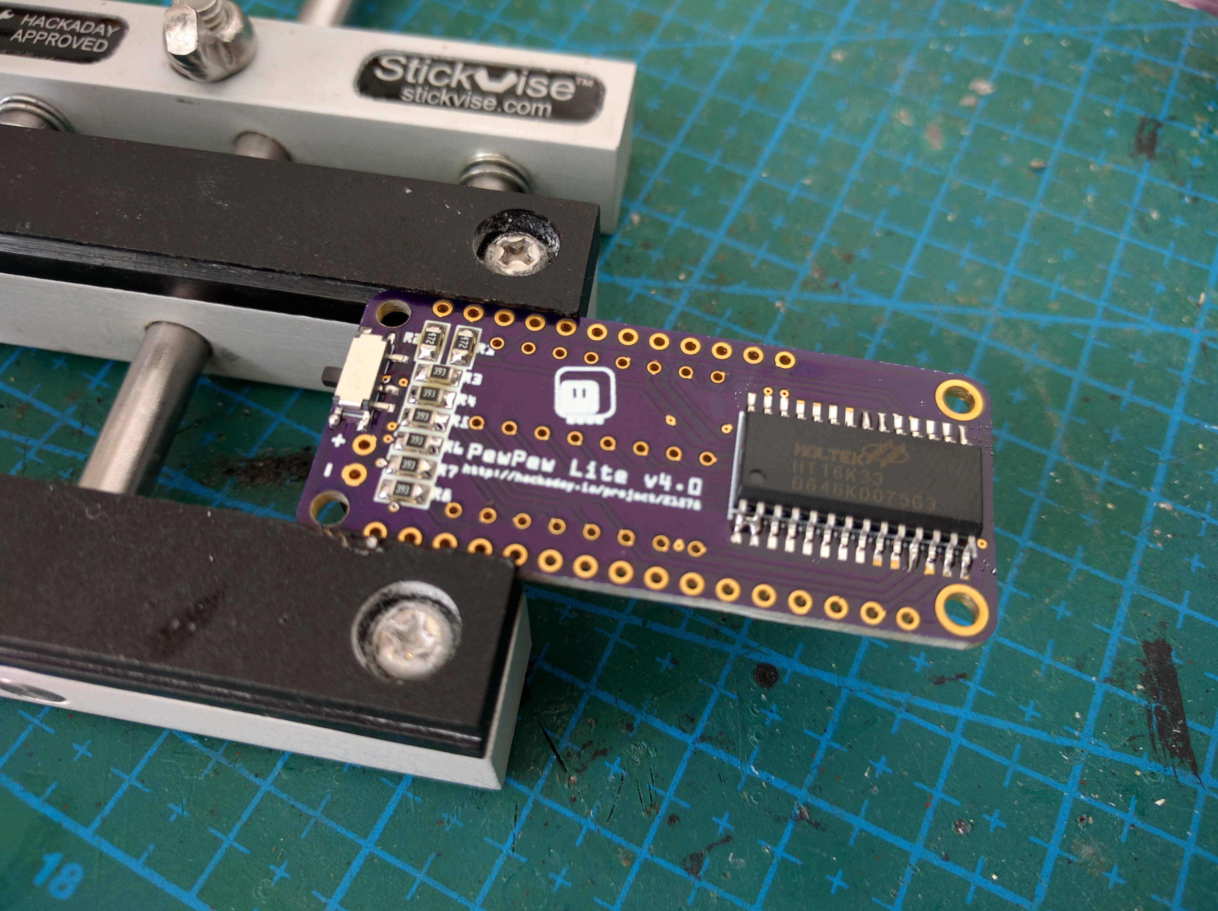
Solder paste for the components
Flip the board, and apply the solder paste to all the pads on the other side.
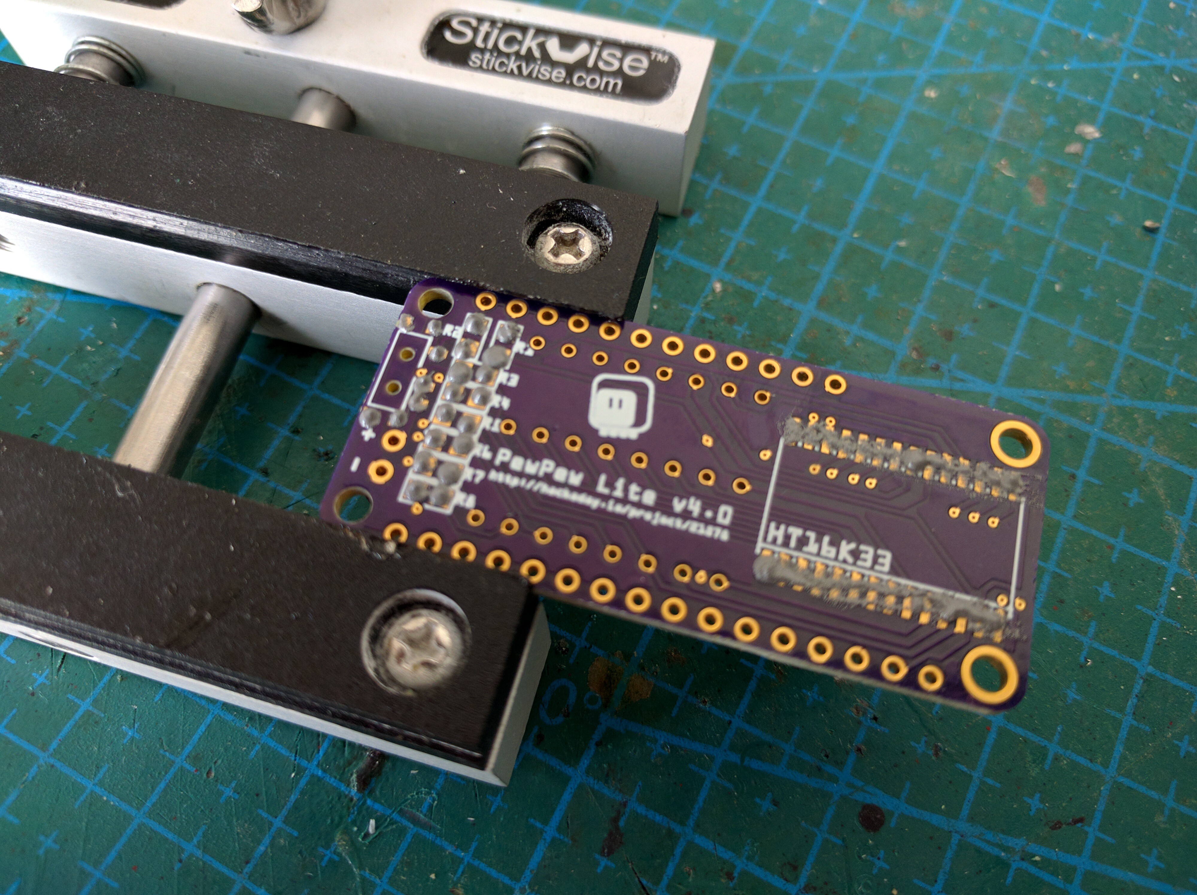
Place components
Place the components. Make sure to align the chip properly — it is also too big to move with the surface tension. Pay attention to the resistor values.
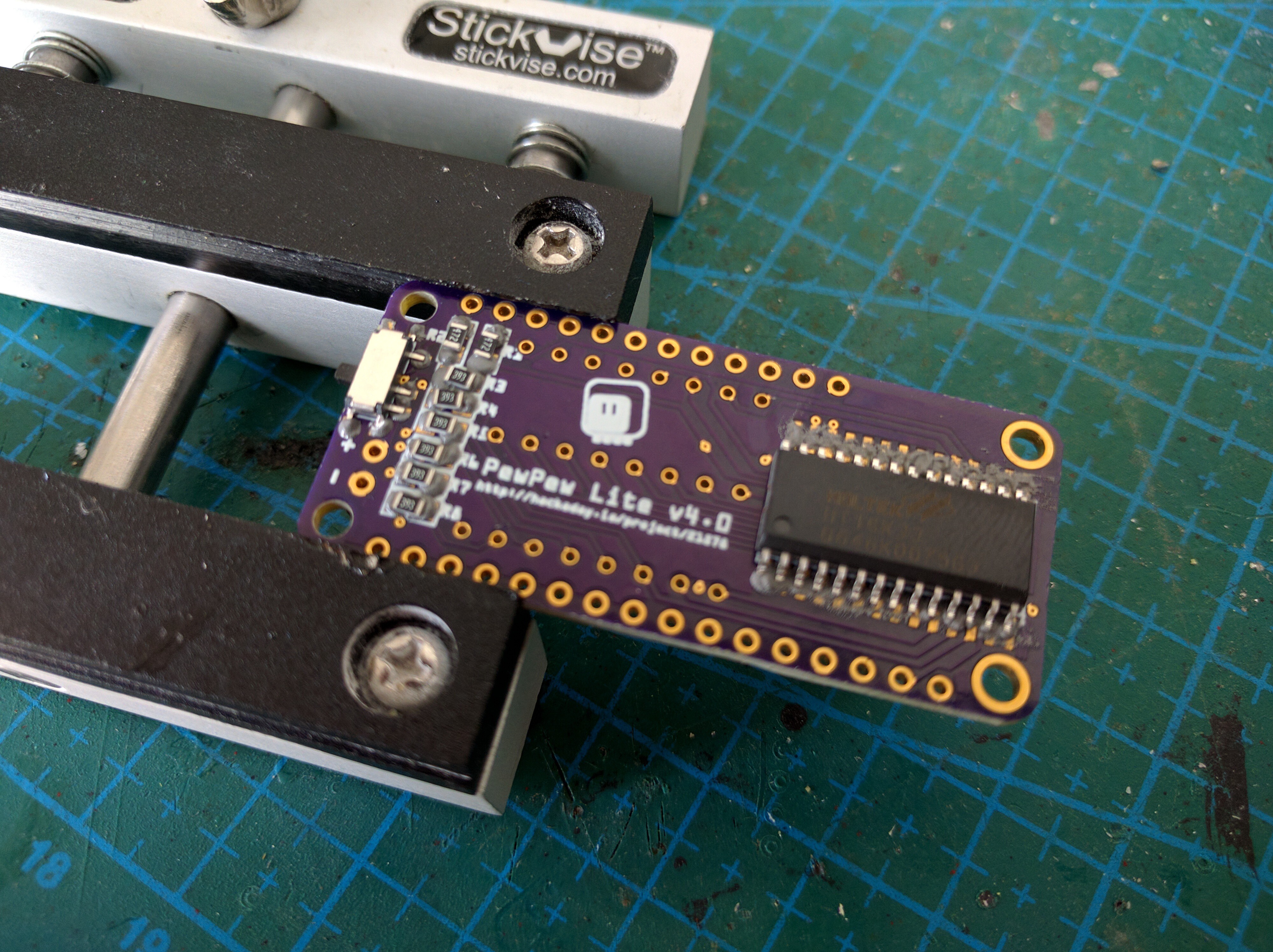
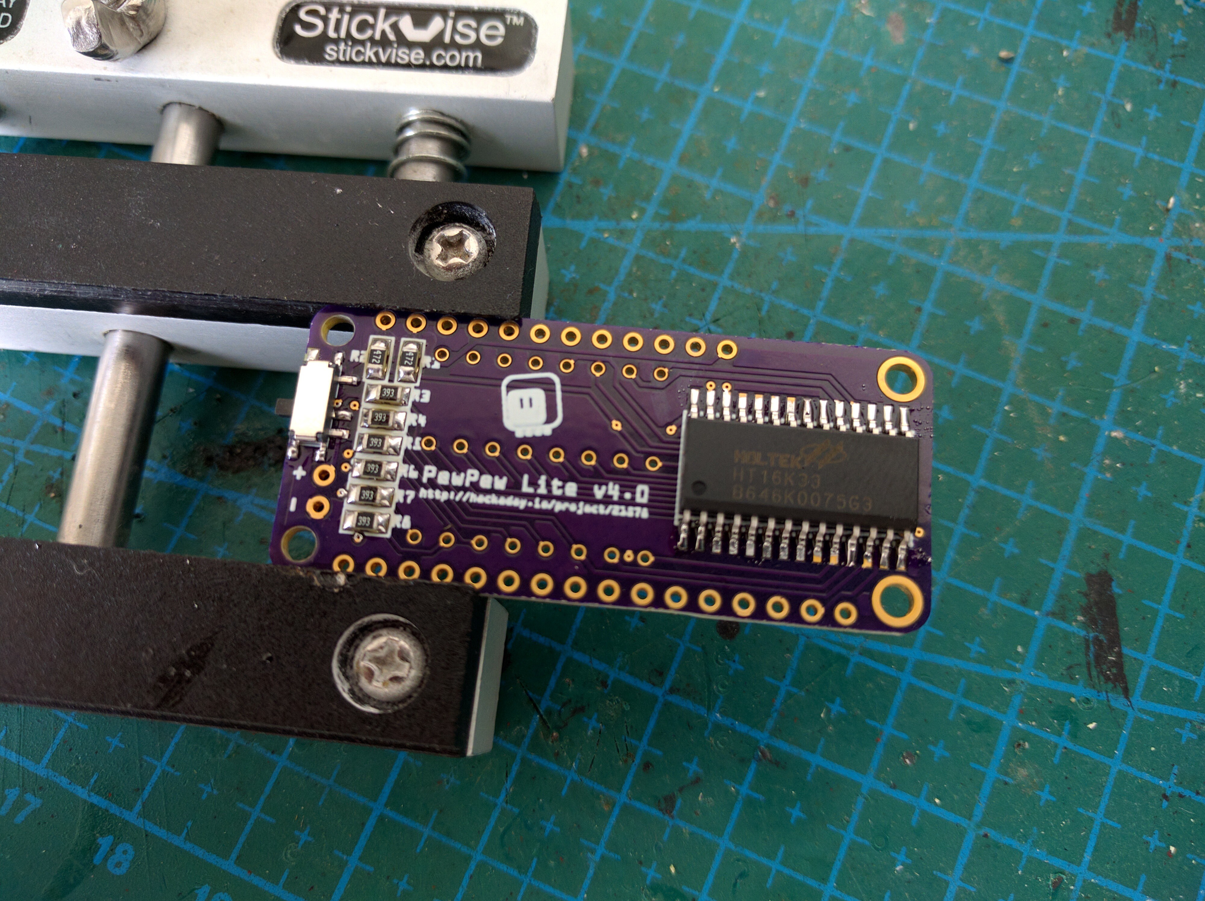
Solder components
Apply the hot air. Be careful to not blow the resistors away.
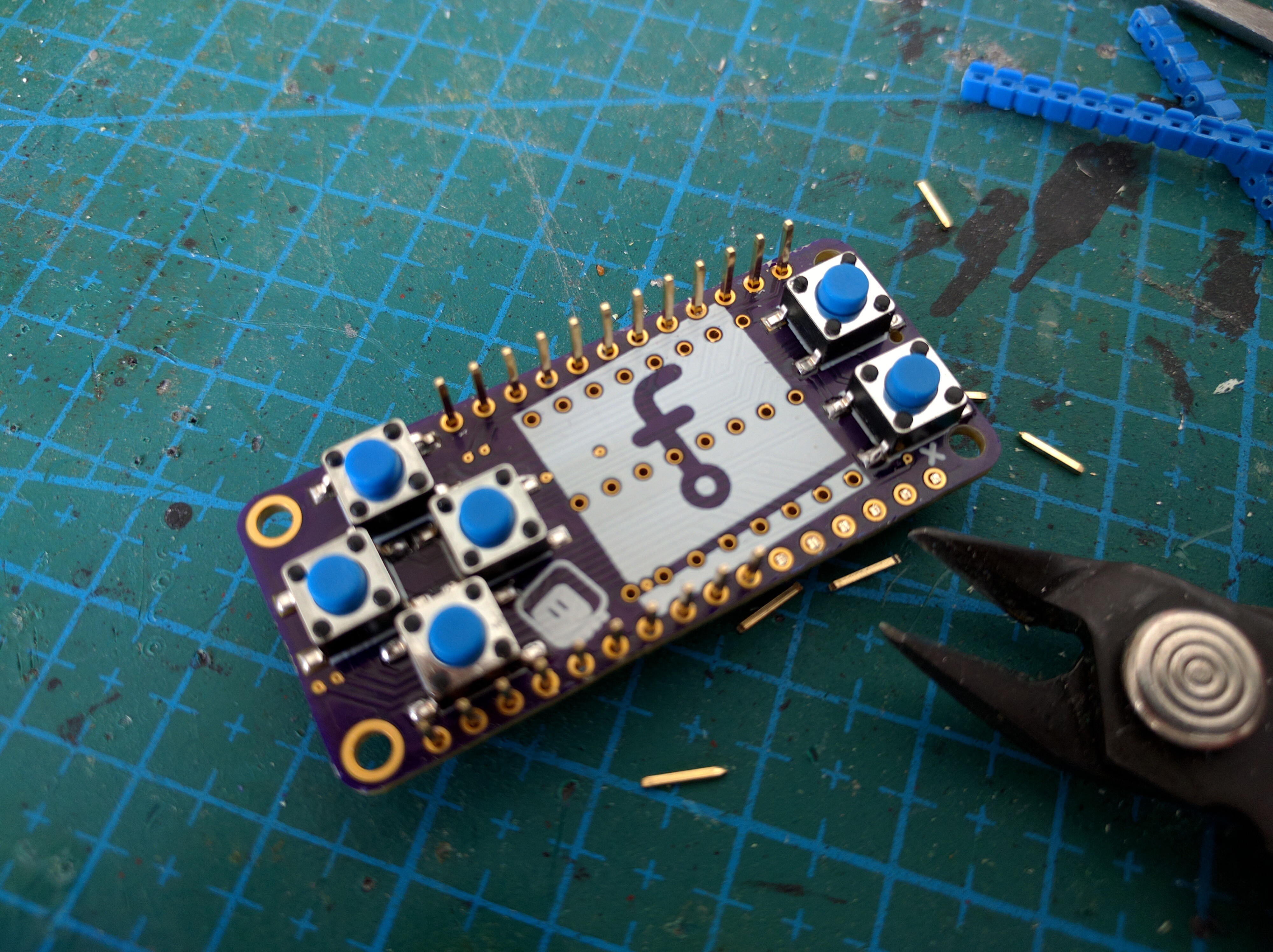
Remove bridges
Use a suction tool or a copper wick to remove any solder bridges you might have gotten, like in this case between the first and second pins of the chip.
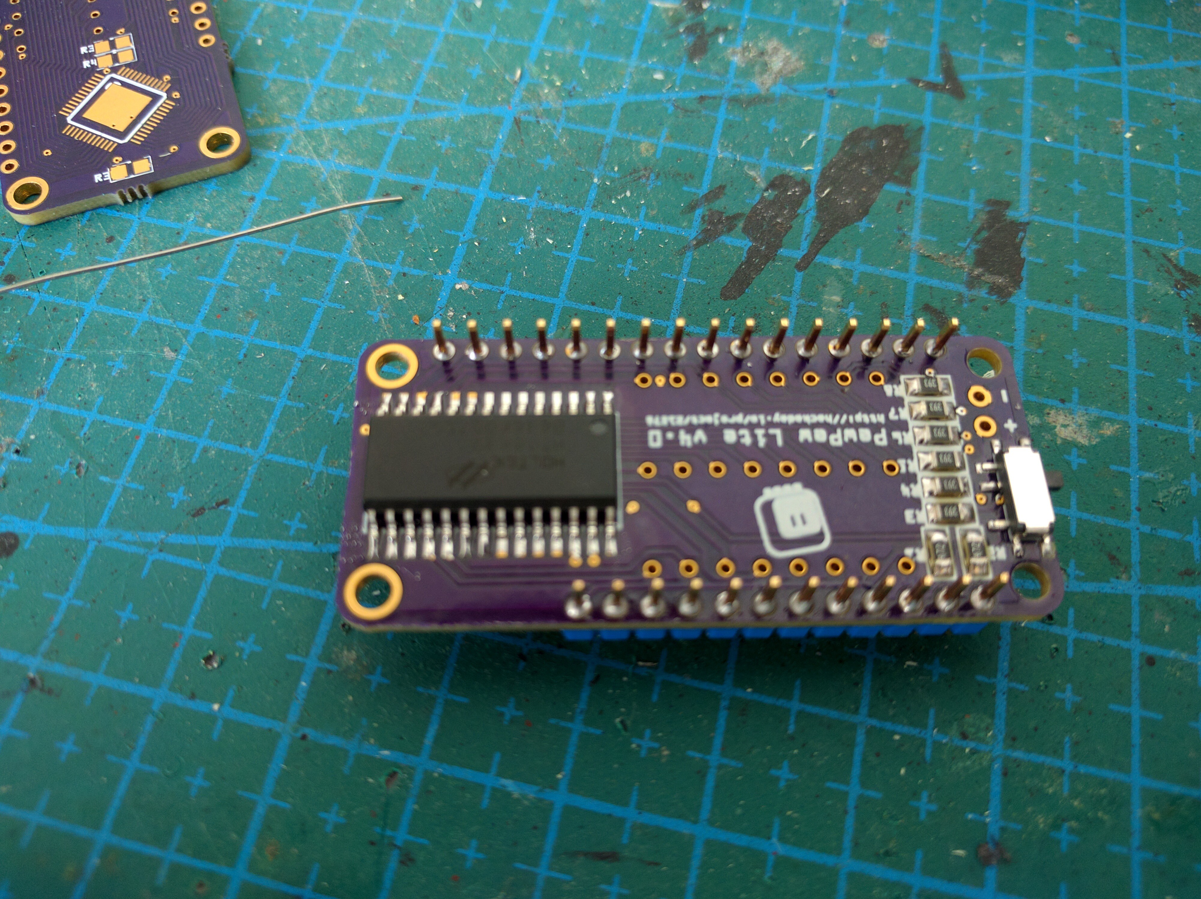
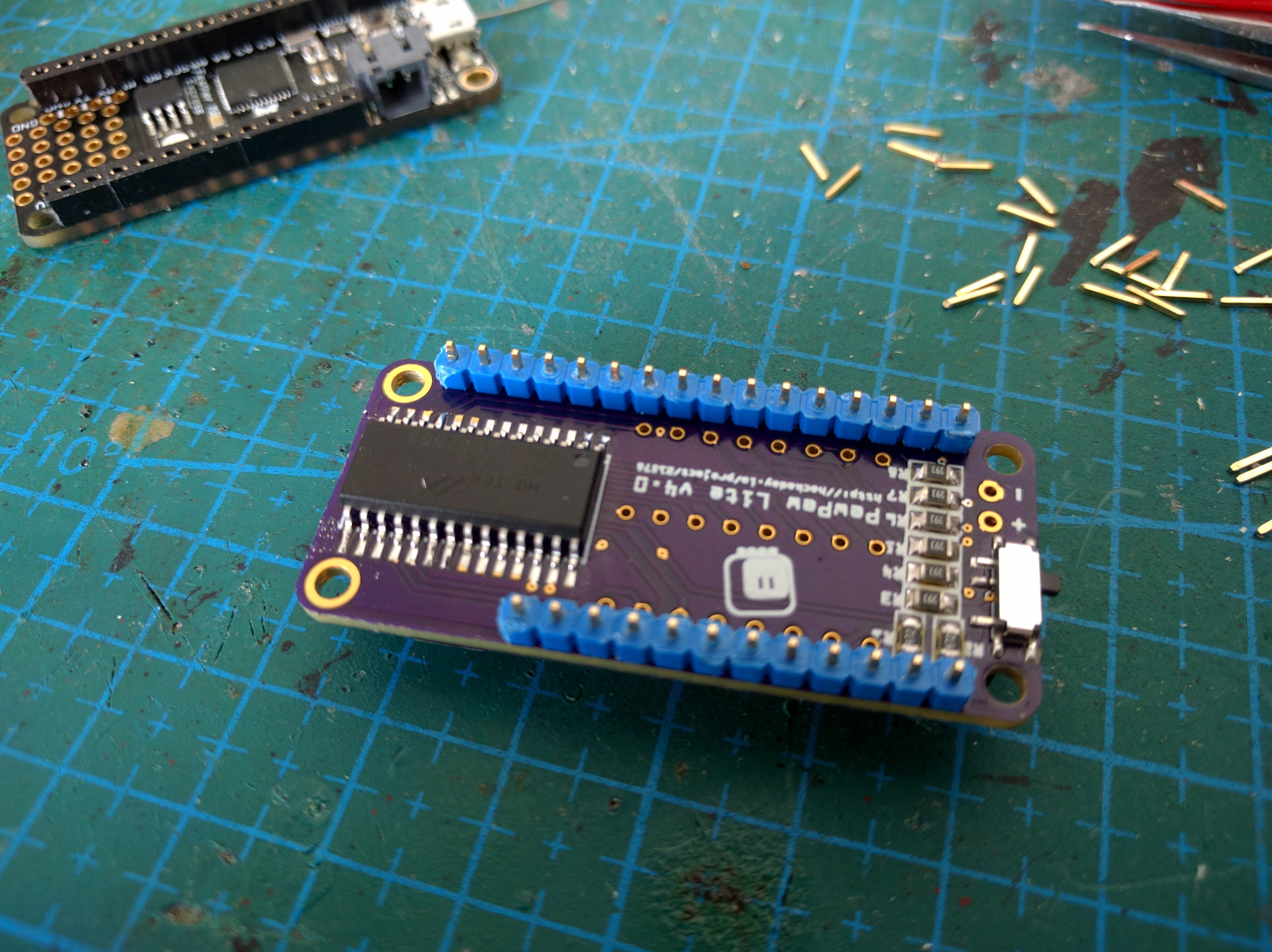
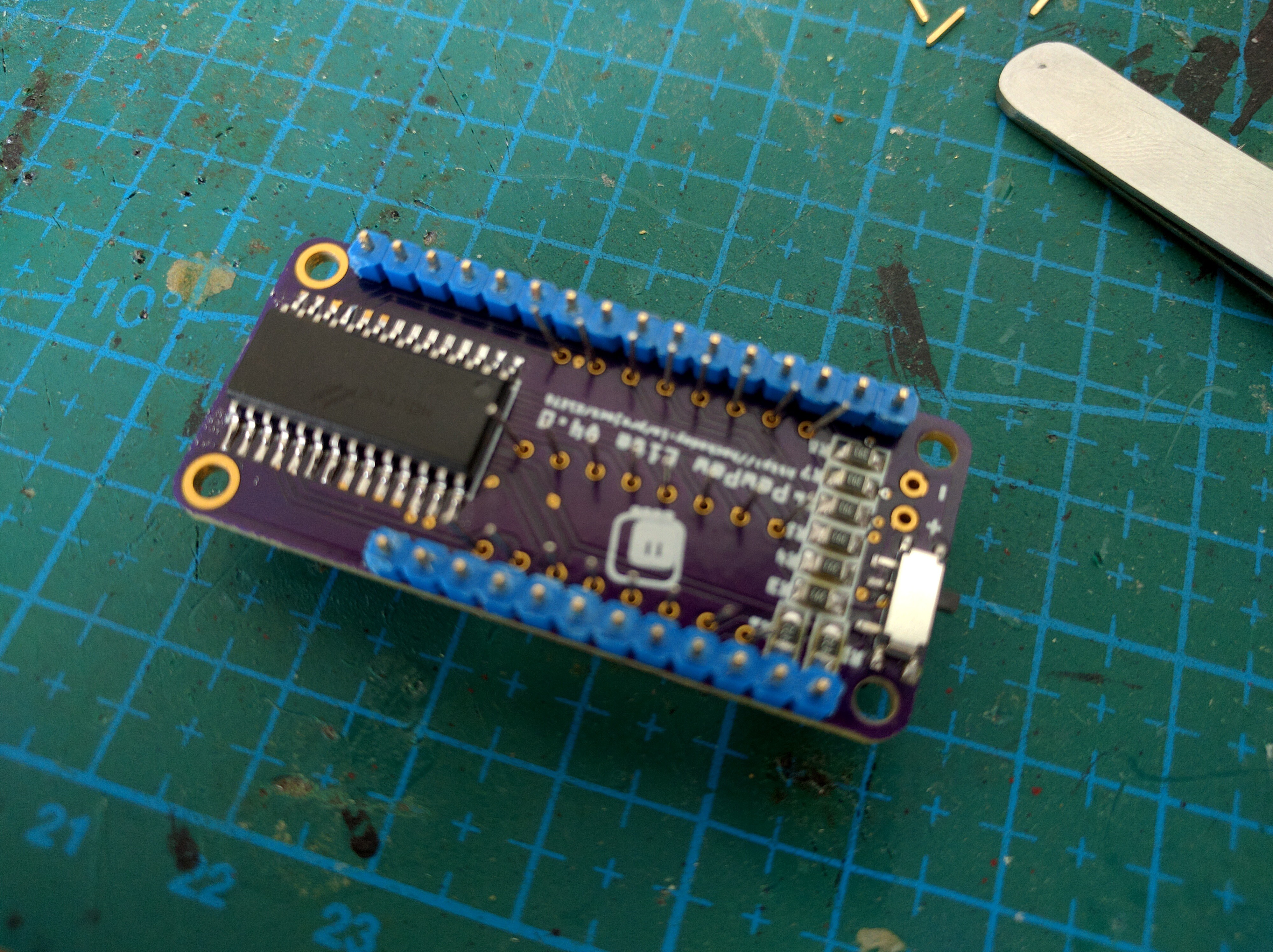
Insert headers
We are going for a low profile look, so we will solder the headers in reverse. Insert the male headers from the top, long side down.
Solder headers
Now flip the board and solder each pin in place. Make sure to not use too much solder and make the joint as flat as possible. Use a suction tool or a wick to remove excess solder.
Remove plastic from headers
Once the headers are all soldered, you can remove the plastic that held them together. Use wire cutters or tweezers to pry it off. Be careful to not damage the buttons in the process.
Trim the headers
Trim the pins, so that the top of the board is completely flat.
Put the plastic back on (optional)
If you are going to use the low-profile female headers on your Feather boards, you can put the plastic back on the pins, since they only need to stick out very little. If you are using regular headers, leave the plastic off, this way the pins can go deeper into the female headers and the whole thing will be thinner.
Insert the matrix
Insert the bi-color LED matrix into the holes. Make sure to make the text on the matrix face down, as pictured here. You will need to use your tweezers to make every pin fit into its hole. It takes some patience.
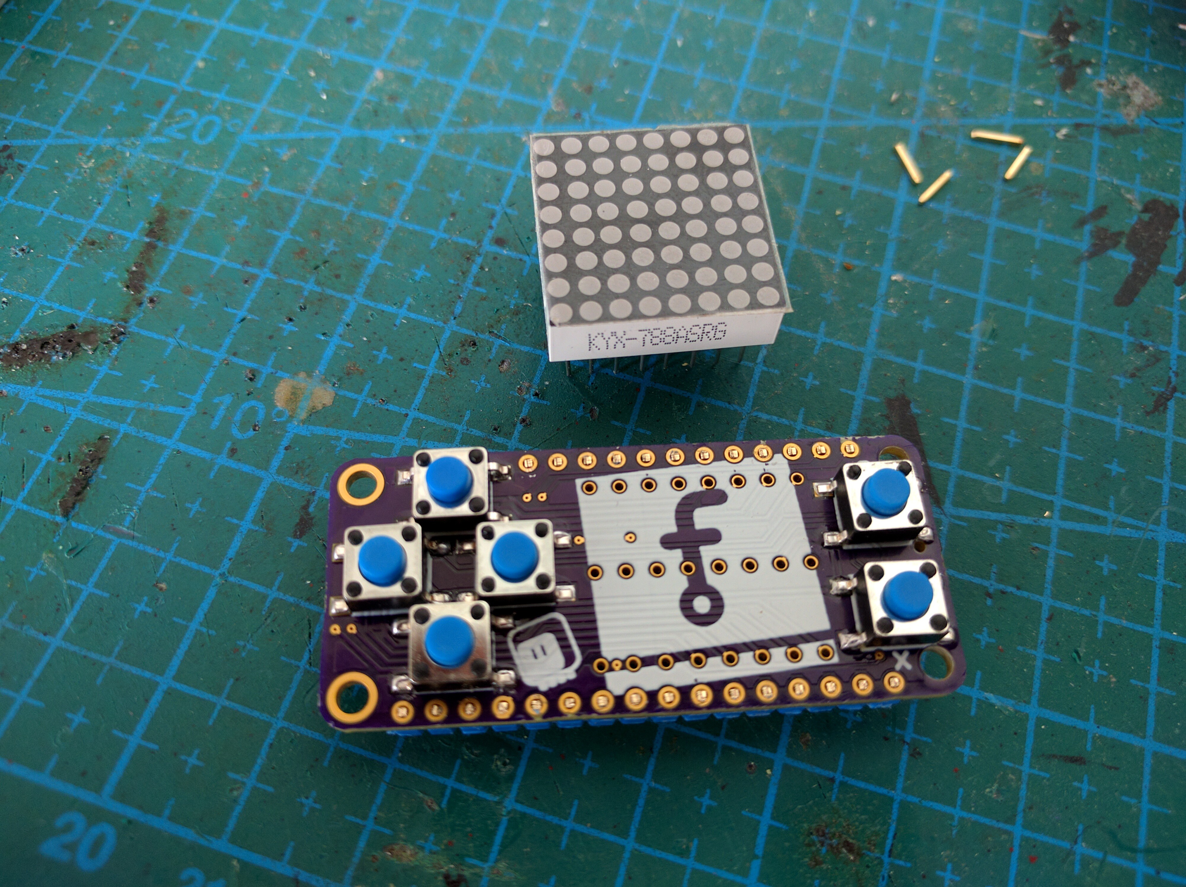
Push the matrix
Push the matrix against a soft surface until it’s flush with the board. Don’t use too much force, or you will break the board or scratch the matrix.
Solder the matrix
Solder all of the pins on the back side. Start with the side ones, and then do the middle.