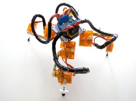
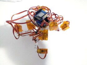
D1 Mini Tote
A version of Tote with the D1 Mini ESP8266 board as a brain.
This is the next step of evolution of Tote and Tote HaD , the spider robots that were designed to be as simple and easy to build as possible, without sacrificing the proper walking algorithms. This time the focus is on making it easier to program and to modify by attaching additional hardware.
While Tote was focusing on building a proper quadruped robot without special materials and tools and as cheaply as possible, the subsequent projects focus on making the robot more reliable and easier to experiment with. The SpiderWing project loosens the budget constraints, aiming to make a sturdier, stronger and more consistently reproducible robot. This project works in parallel to that, trying to incorporate the same improvements, but without rising the price too much. The two projects are meant to cover the conflicting needs of hobby robot developers.
Of course, the overarching goal for both of them is to stimulate research in affordable and reliable legged robots, so that we can have devices like this at our homes one day.
Logs
2019-05-08 - One More Version
2017-06-15 - Sturdier Legs
2017-06-14 - More Brain Power
2017-02-20 - Battery Protection
2017-02-18 - Smaller ATmega
2017-01-29 - Debugging
2017-01-26 - Surprise PCBs
Links
Components
Component |
Count |
Notes |
|---|---|---|
D1 Mini ESP8266 development board |
1 |
|
3.7V 1S LiPo battery |
1 |
|
SPDT Switch |
1 |
|
SG90 Microservo |
12 |
|
M1.2x4 screws |
24 |
|
10x1 2.54mm pitch male pin header |
6 |
|
8x1 2.5mm female pin header |
2 |
|
Battery Holder |
1 |
|
(optional) Battery protection circuit |
1 |
|
PCA9685 PWM Chip |
1 |
|
Custom PCB |
1 |
|
Resistor 0805 4.7kΩ |
2 |
Instructions
Mechanical Assembly
For mechanical assembly, follow the instructions at http://tote.readthedocs.io/en/latest/assembly_v5.html#legs
Electronics
Solder the headers, PWM chip and resistors onto the board. Add the power switch and battery holder. Connect the servo plugs.
Programming
Copy the python code from project’s repository onto your D1 Mini using Adafruit’s Ampy utility. Plug the D1 Mini into the PCB.
Extending
Use the D1 Mini’s headers to add shields with sensors and other components to the robot. Modify the code to take advantage of them.
 deshipu.art
