The Legs
Published on 2024-07-03 in Bigbug.
It took a while (because I picked the cheap and slow option), but the leg parts finally arrived.
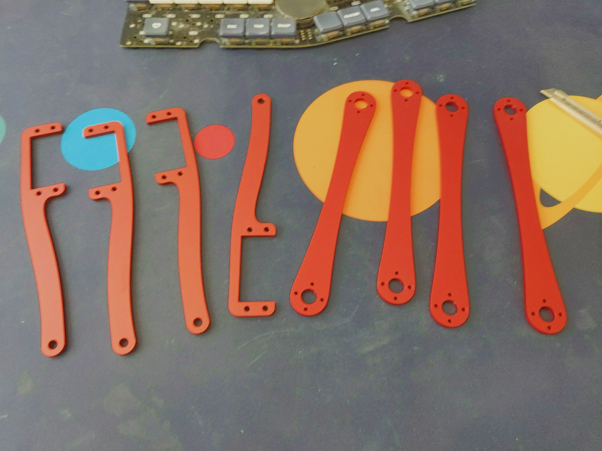
They look great: 3mm thick anodized aluminium. Very solid and pretty light too. So I assembled the robot with the PCB body first, just to see how it all looks like:
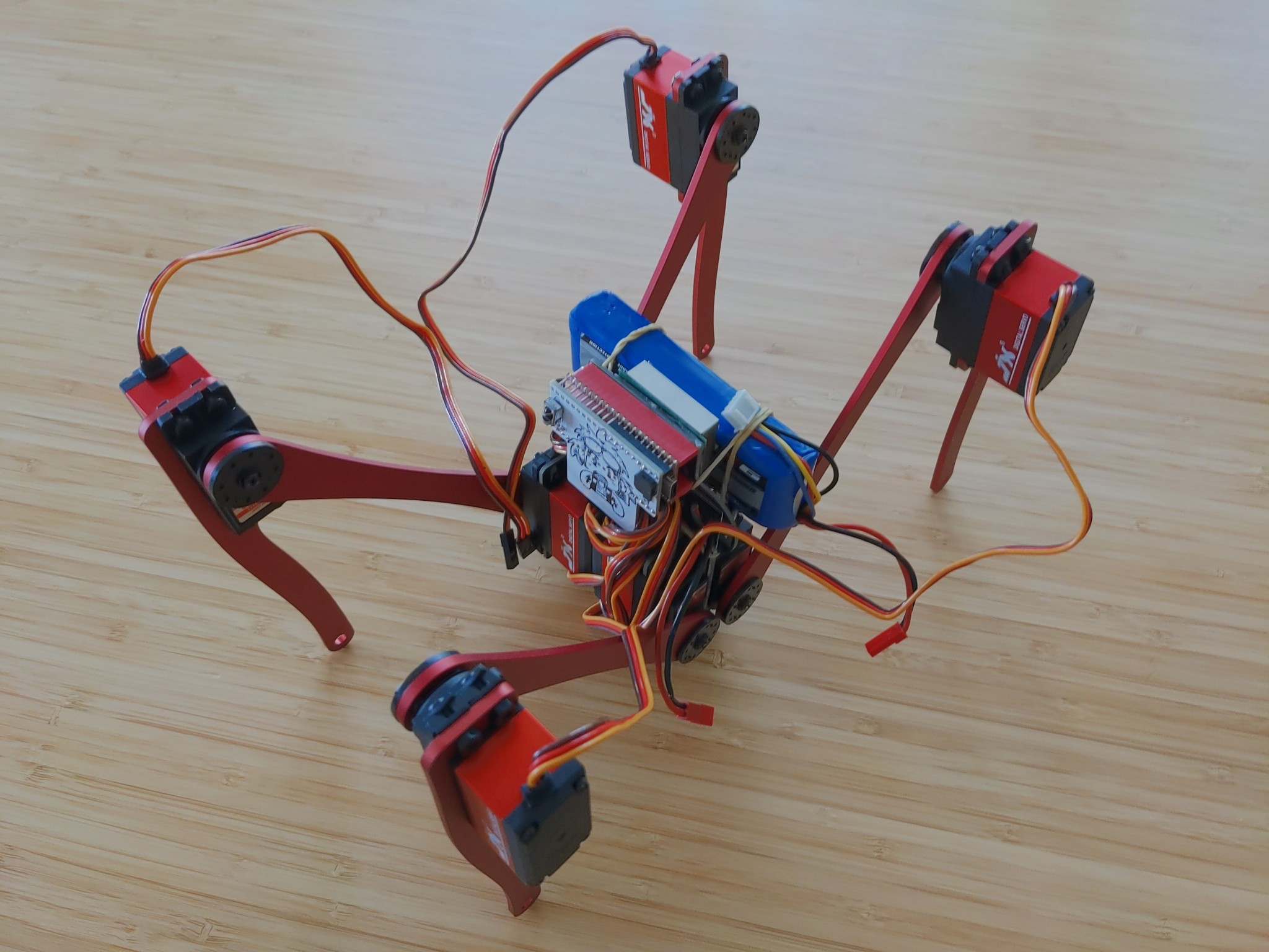
Turns out that those servos are really beefy. In fact, they are so strong and fast, that my lazy code, which tells them too move from one end to the other when making a step, makes them draw so much current that the 8/15A regulator shuts down. This is more of a software problem, though, than hardware — the power is perfectly adequate when the servos are moving more gradually and don’t make sudden movements all at once. There is also a problem that I already noticed in the first version of Big Bug, that is even more pronounced now with the longer legs — the robot is tilted to one side for some reason. I initially thought that it’s because the servos have asymmetric response to the PWM signal, moving faster in one direction than in the other, but then the difference would be between diagonal legs, and it’s clearly a left/right asymmetry. I will need to investigate that closer.
With the initial tests done, I proceeded to move the robot to its proper aluminium body.
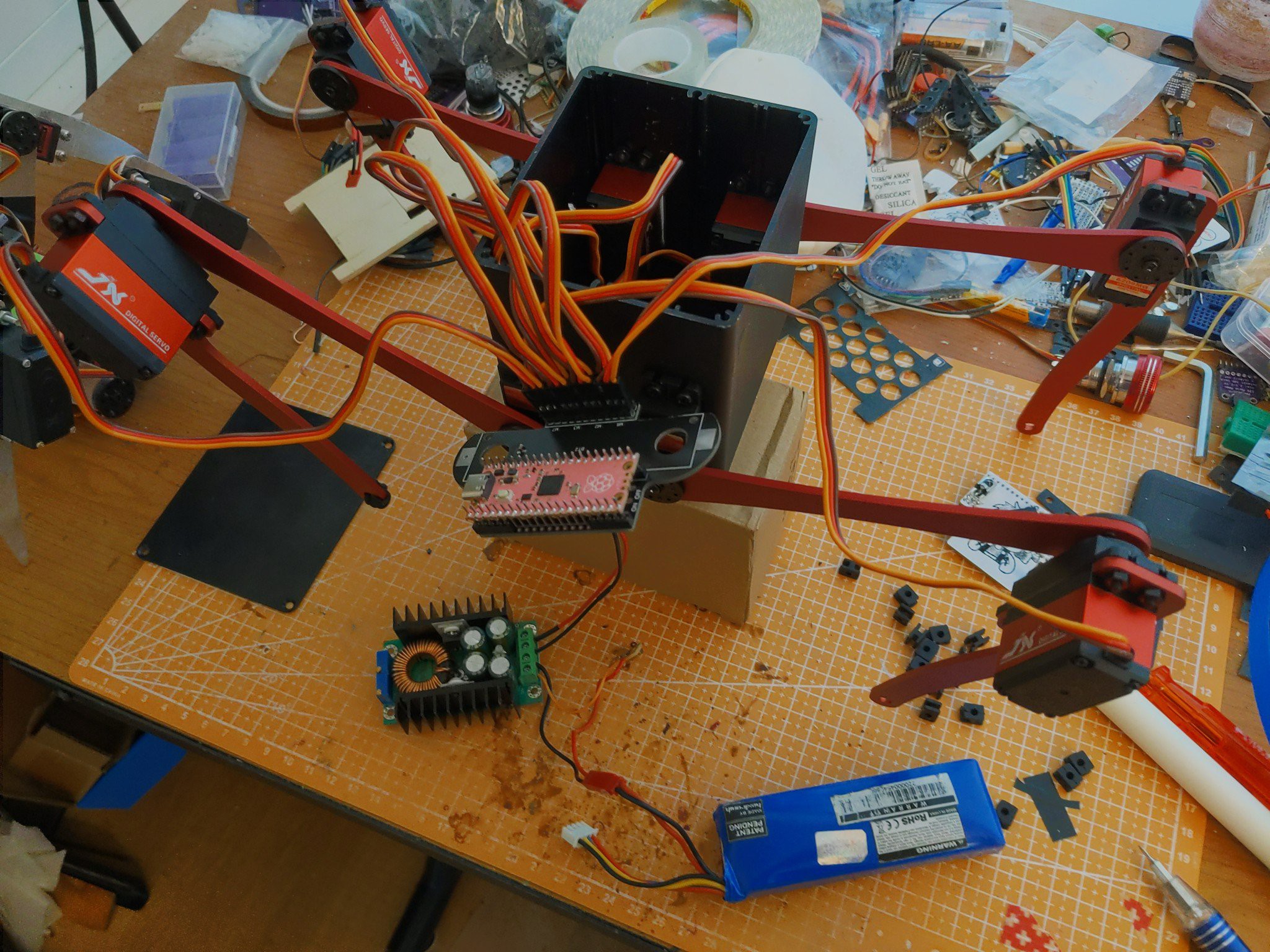
I used one more spare PCB from the PCB body, but I cut off the mechanical part to which the servos were attached, so that it will fit inside the case better. I also experimented with several different buck converters, but in the end settled on the 8/16A one that I used initially. I ordered a few more to try later, too, so I might still change it.
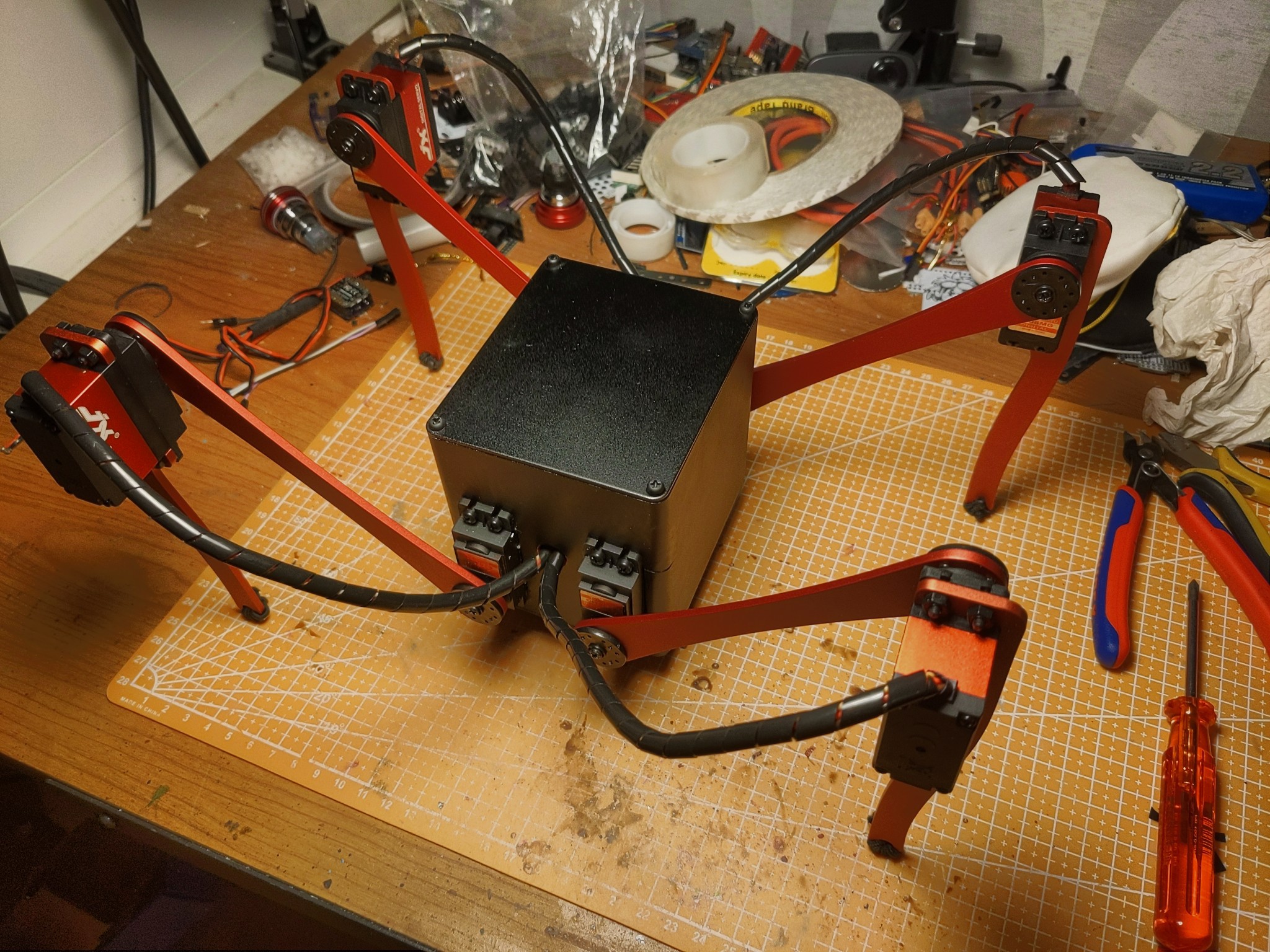
The total weight of the whole robot is just shy of 1kg, which is not too bad. I might actually make it even less by replacing the case lids with PCBs (I don’t feel like drilling all the holes for the power switch and USB in the original lids), and using a smaller battery.
I drilled the holes on the sides for the servo cables, added some plastic cable management thingies, wrapped some rubber strings on the feet, and closed the lid:
Now all that is remaining is, as always, programming. And waiting for the additional parts.