Version Two
Published on 2024-06-20 in Bigbug.
The robot was built to see if it would work, and I have to say that it worked pretty well so far. However, after taking it to several different events, I now have some ideas about how to improve it for such events specifically.
The main problem I have is that the robot is really to slow to walk around with it. As such, it’s mostly spending its time on the time, waiting to be switched on for a few steps to show to the passing people, and switched off before it falls off the table. Its size is also a bit awkward. It’s too big to really do anything useful on the table, but too small to be safe from being trampled on the floor.
So now I want to build a second version, using faster servos and longer legs. That should solve both the problems. I also want to try and make the body look less like a bunch of duct-taped garbage, but that’s a secondary consideration.
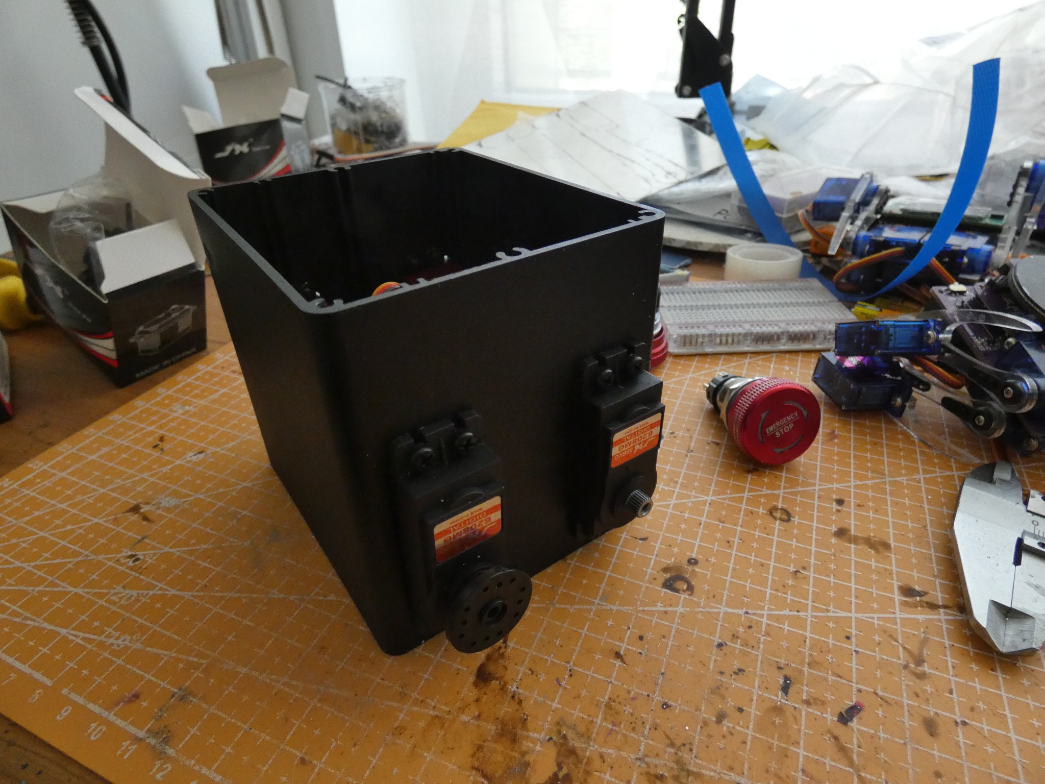
I already have the servos for the second version. I went with the JX PDI-6208MG, mostly because they are roughly the same size as the MG995 I used in the first version, but should be about twice as fast. I also got some aluminium cases to see if I can use them as the body. One such case seems to be particularly suitable, so I went ahead and cut some holes in it to mount the servos:
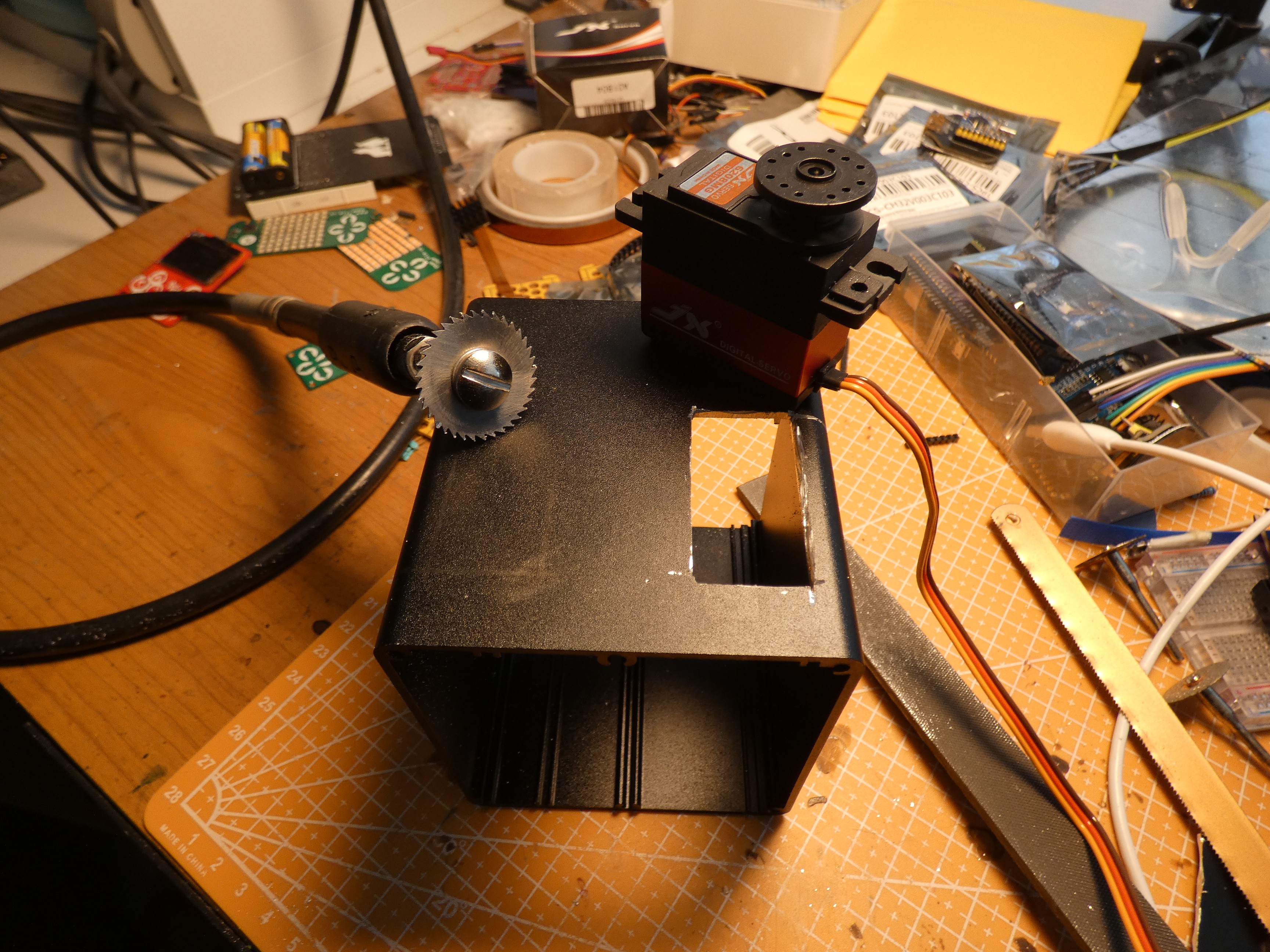
Cutting thick aluminium with a dremel turned out to be harder than I anticipated, but with some struggle, I got all four holes for the servo, and the accompanying mounting holes done, and then painted the enclosure with black spray paint to make all the scratches less obvious.
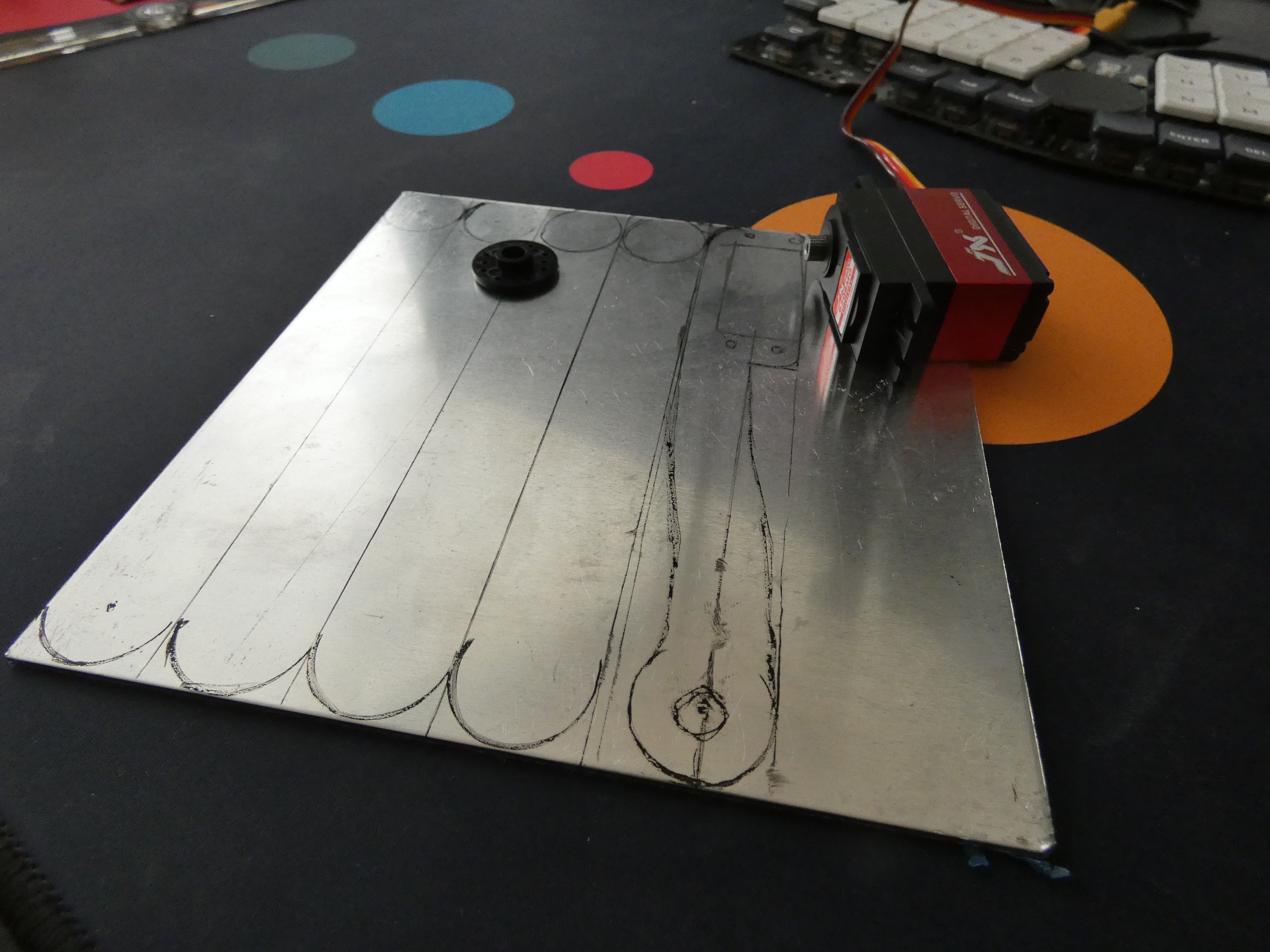
As for the legs, I was planning to cut them from 3mm sheet aluminium again, but then I realized that some of the usual PCB fabs also let you order CNC cut parts. Initially I tried three of them, but with the pricing they showed, I started preparing the hacksaw.
But then I thought about the fact that they also do bead-blasting and anodizing of the parts. I imagined nice red anodized aluminium legs, and I went to try some more fabs. One of the offered to make the parts for 1/3 of the price of the others, and that is acceptable for me for a one-off project, so I ended up ordering the parts anyways.
They wanted step files, so I took this opportunity to learn to use FreeCAD a little bit…
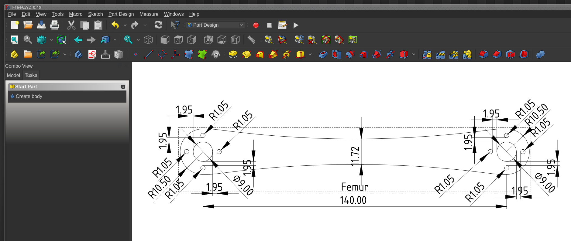
I know, I know, this is horrible. But it’s the step file that counts in the end. With the leg parts ordered and scheduled to arrive in some two weeks, I got to work on the electronics.
I don’t need anything too fancy here. I wanted to use the pi pico, to have enough extra pins for things like speakers, blinking LEDs, extra moving parts and so on. I considered using a 3S lipo battery pack, but it’s considerably heavier than the 2 18650 batteries I used previously, so I kept those. I looked at the buck converter chips available, but I didn’t find anything that would be much better than just using a ready buck module, so I just left holes to connect that. The rest is simple: power switch, servo sockets, and a shottky diode for the pi pico VSYS (I might replace it with a different diode with a larger voltage drop, to raise the voltage for the servos).
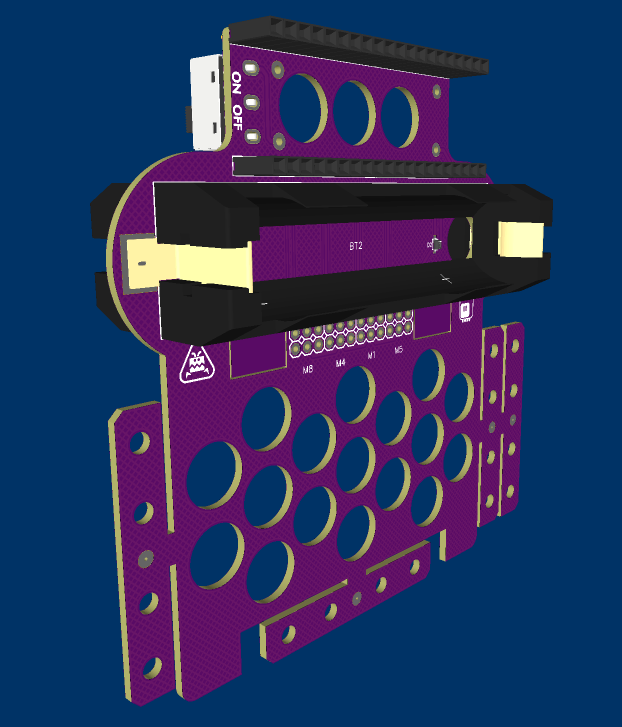
Just in case, I made the PCB shaped just like the body of the robot in Wee Bug and Fluffbug , so that if the aluminium case proves to be too heavy or otherwise problematic, I can revert to the taped garbage looks. I moved the batteries to both sides of the PCB to make the weight more evenly distributed, and I added a bunch of break-off parts for attaching the servos.
Now with the PCB and the leg parts on order, all we have to do is wait.