New Body in Action
Published on 2023-08-27 in Wee Bug.

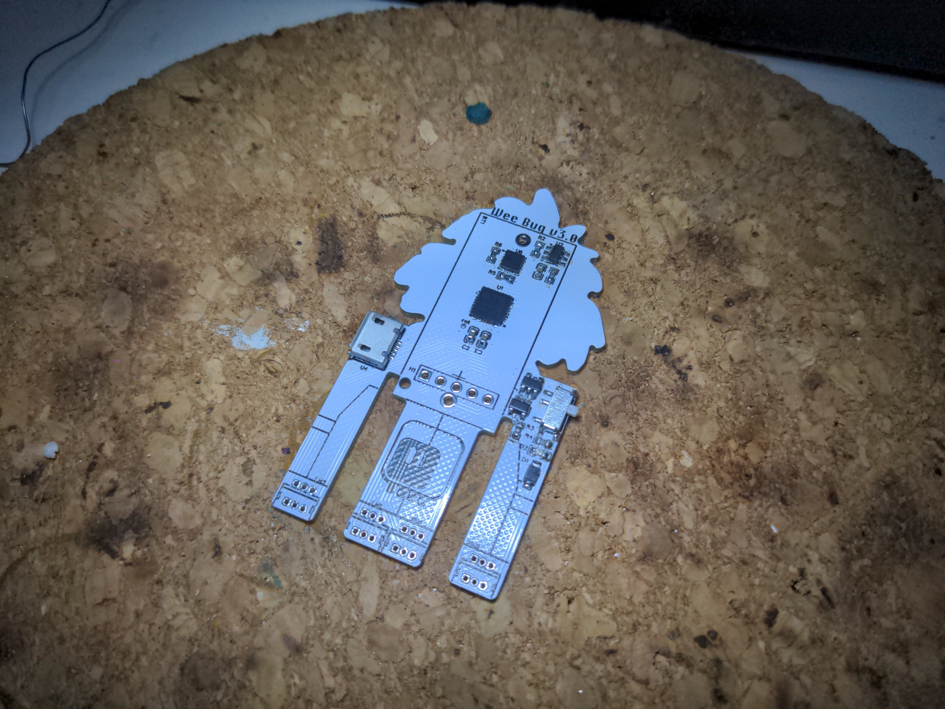
As always, the PCBs arrived from JLCPCB, so I went ahead and assembled one. I had some fun soldering the accelerometer chip – it’s QFN, but it was lying in my drawer for a few years, and apparently some of the pads got oxidized. Only after I went over them with a hot iron and flux, the soldered correctly. Good thing I decided to test the chip before I soldered the battery holder, because the chip is underneath it, and it would be a pain to have to desolder the holder first. Also, I was afraid that the THT servo sockets will be hard to solder on both sides of the PCB, but turns out they are far away from each other enough to not interfere with soldering. Phew. I still don’t think I could make a fab do this, so if I ever decide to do a workshop with this robot, I will have to switch to SMD sockets.

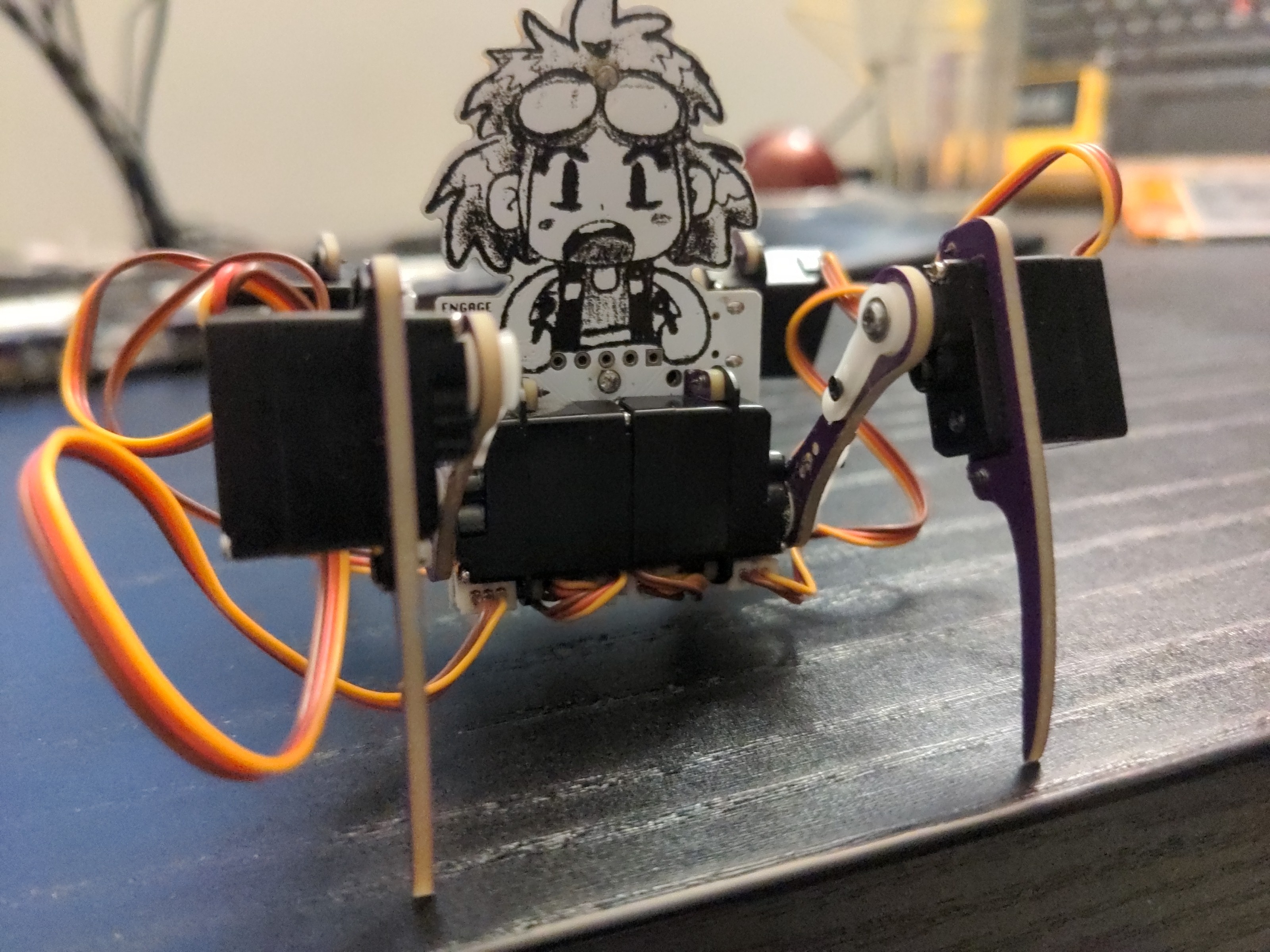
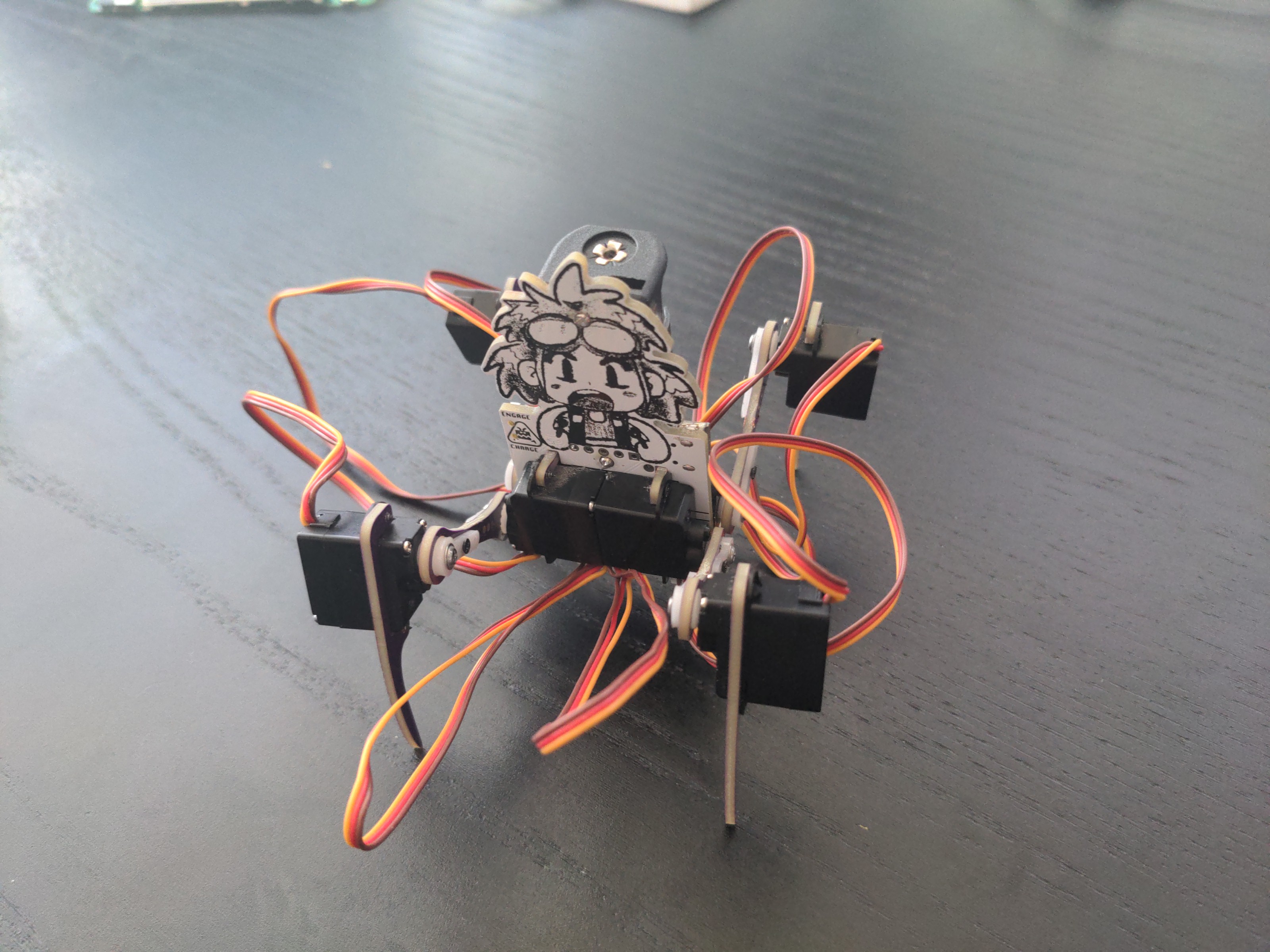
After it was all soldered, the UF2 bootloader flashed, and CircuitPython firmware uploaded, it was time to assemble the legs. And here’s the first mistake: I made those long slots in the PCB hoping that I will be able to stuff at least some of the servo cables in there, to make it look a little cleaner. But I didn’t anticipate how small this PCB is, and the cables simply don’t fit in there. Oh well. If I ever make another version, I will remove the slots, leaving only the parts necessary for servo mounting. That will also make routing of the traces easier.

With the legs connected, the servos zeroed and the initial leg positions calibrated, I copied some of the old code for walking (the SAMD21 build of CircuitPython doesn’t include async functionality that my newer code uses), and it walks. I just had to change the order in which the legs are initialized, so the right timers get assigned to their PWMs. However, I found further mistakes.
First of all, the switch that switches between walking and battery charging is reversed, so the labels are wrong. Not such a big deal, I suppose, and I could easily enough fix it by swapping the labels.
I also thought that I made a second mistake, connecting the USB power so that it powered the servos, but that was just a mistake in soldering the shottky diode in reverse. After flipping it, the servos are now correctly only powered from the battery, so I can program the robot when it’s switched to charging mode, without worrying about it making random movements.
The next steps now may involve using the accelerometer for interesting things, doing something about the cables (I need to open one servo and see if I can easily shorten the cable from that side), and seeing if I can enable async on this build, possibly at the cost of disabling some of the built-in modules that I’m not using.
 deshipu.art