PCB Design
Published on 2022-12-31 in Wee Bug.
I measured the servos, and quickly designed a PCB similar to the one used in Fluffbug , but proportionally smaller.
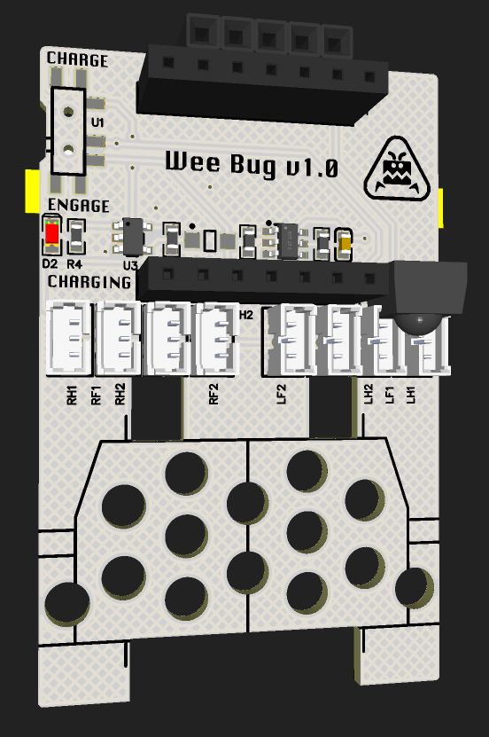
I gave up on the IDC connectors for the servos, and just went with the 1.25mm JST sockets. Instead of the Lolin S2 Mini, I decided to use either the Adafruit Qt Py board, or Seeedstudio Xiao – as it happens, they have the same pinouts, so I can decide later, or even switch between them. All the rest is pretty much the same as in Fluffbug, but since there was some free space, I also added a footprint for an optional infrared sensor, so that I can use a tv remote to control the robot.
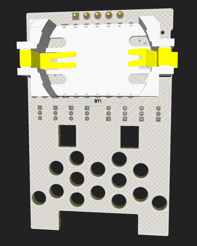
The last problem is the battery. I didn’t want to use the pouch lipo batteries, because they are not standard and pretty dangerous, so I looked at what standard battery size would fit it. Eventually, I decided on LIR2450 (or the bigger LIR2477 version), and added a coin cell battery holder to the PCB. The contacts stick out a bit, but I can just cut them.
Of course as my luck has it, as soon as I ordered the PCBs, I found out the perfect battery size that would make it look exactly as Fluffbug, only smaller: the 14250 cells. There is even a holder for it that looks identical to the one in Fluffbug, just smaller:
__
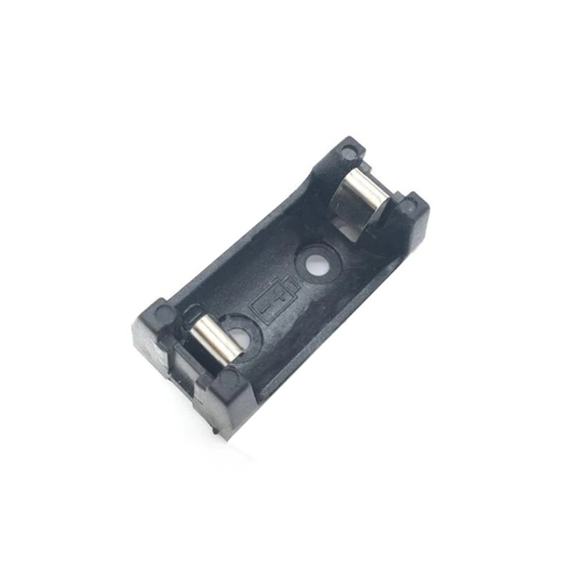
Just look at how cute it is! In the end, I decided to order some of those cells and holders as well, and I will try to bodge them on the PCB somehow.\