The PCB Design
Published on 2022-12-30 in Moo Bug.
This is my first project where I completely switched to EasyEDA as a PCB design tool. I honestly tried KiCAD several times over the years, and it’s just so hilariously bad at exploring designs, that I gave up on it. EasyEDA is still far from ideal (especially the copper fills), but it’s not completely unusable.
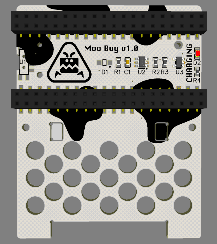
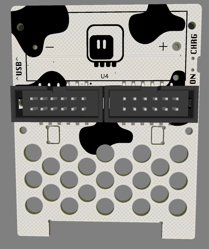
In any case, I followed up on my fluffbug work, of course, but I made everything except for the battery holder surface-mount. I found some pretty nice low-profile smd female headers on LCSC, and the IDC connectors for the servos also exist in SMD versions. This actually gives me much more room on the PCB, because headers no longer take up both sides.


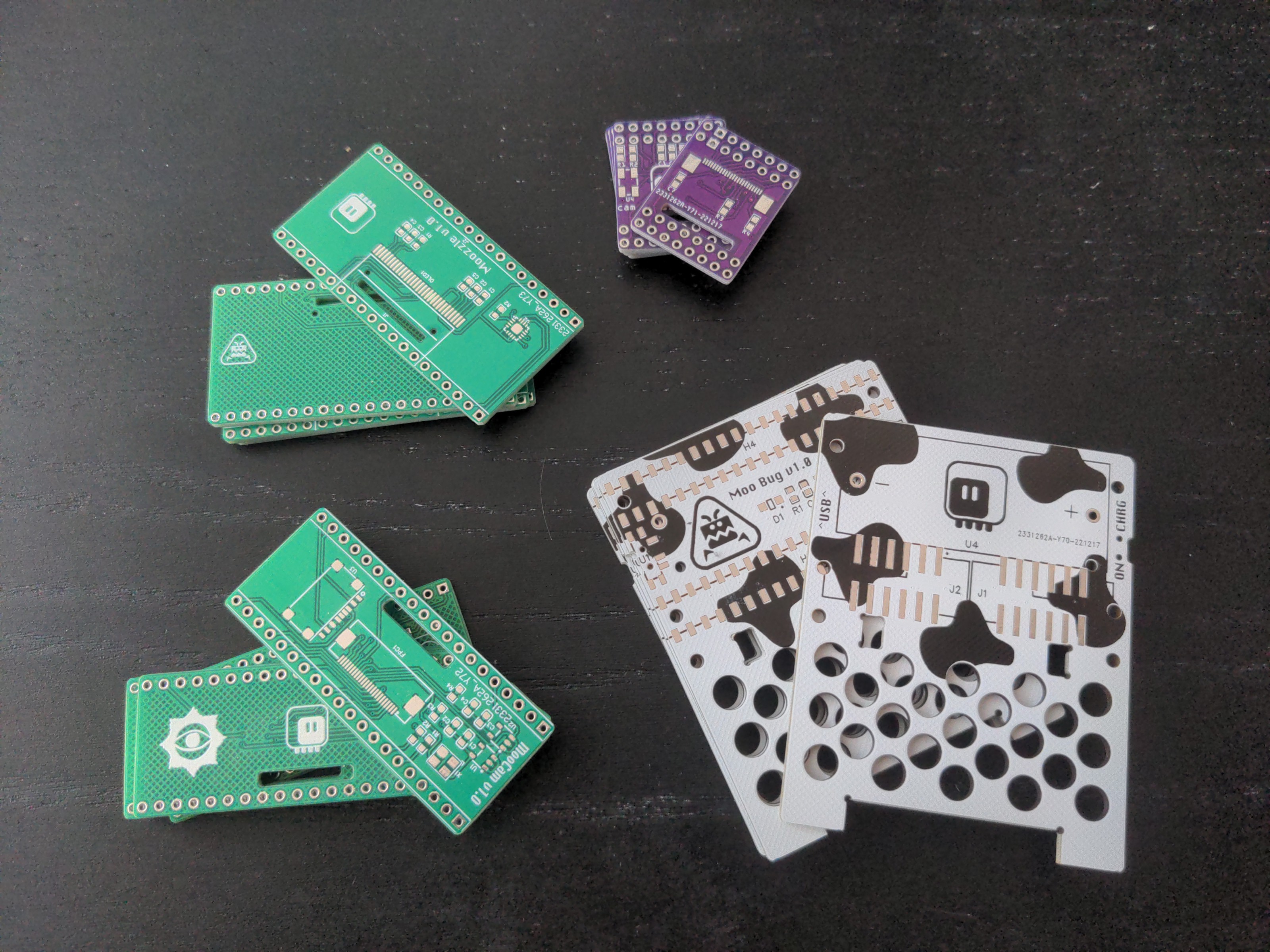
There are still a few pilot holes for all the components, so there was some work squeezing it all to fit, but in the end it came out rather compact. Since the headers are double-row, I can use them to add bigger “face” shields for the robot, with things like displays, cameras, sensors or speakers. In fact, I went ahead and designed two shields, one the size of the pico with a camera, and one bigger, with an oled display and a speaker.

 deshipu.art