Case Assembly
Published on 2022-09-03 in µGame 22.
A few weeks ago I ordered custom transparent stickers for the backside of the front plate for the case, so that they would mask away a part of the display, but more importantly, also hold in place the button caps. They just got back to me with a proposition of a “design” they made from the files I have sent them, where they just took the image of the outline of the sticker I wanted, and printed it on the sticker as the image. Of course that is not acceptable, I didn’t want them to design a sticker based on my graphics, I have sent them an already designed sticker to make. No response from them yet, but I fear that if it’s going to be a few weeks for every back-and-forth, it’s going to be faster to just cut the stickers from a scotch tape myself. So I did exactly that, and in the process documented how the case is assembled.
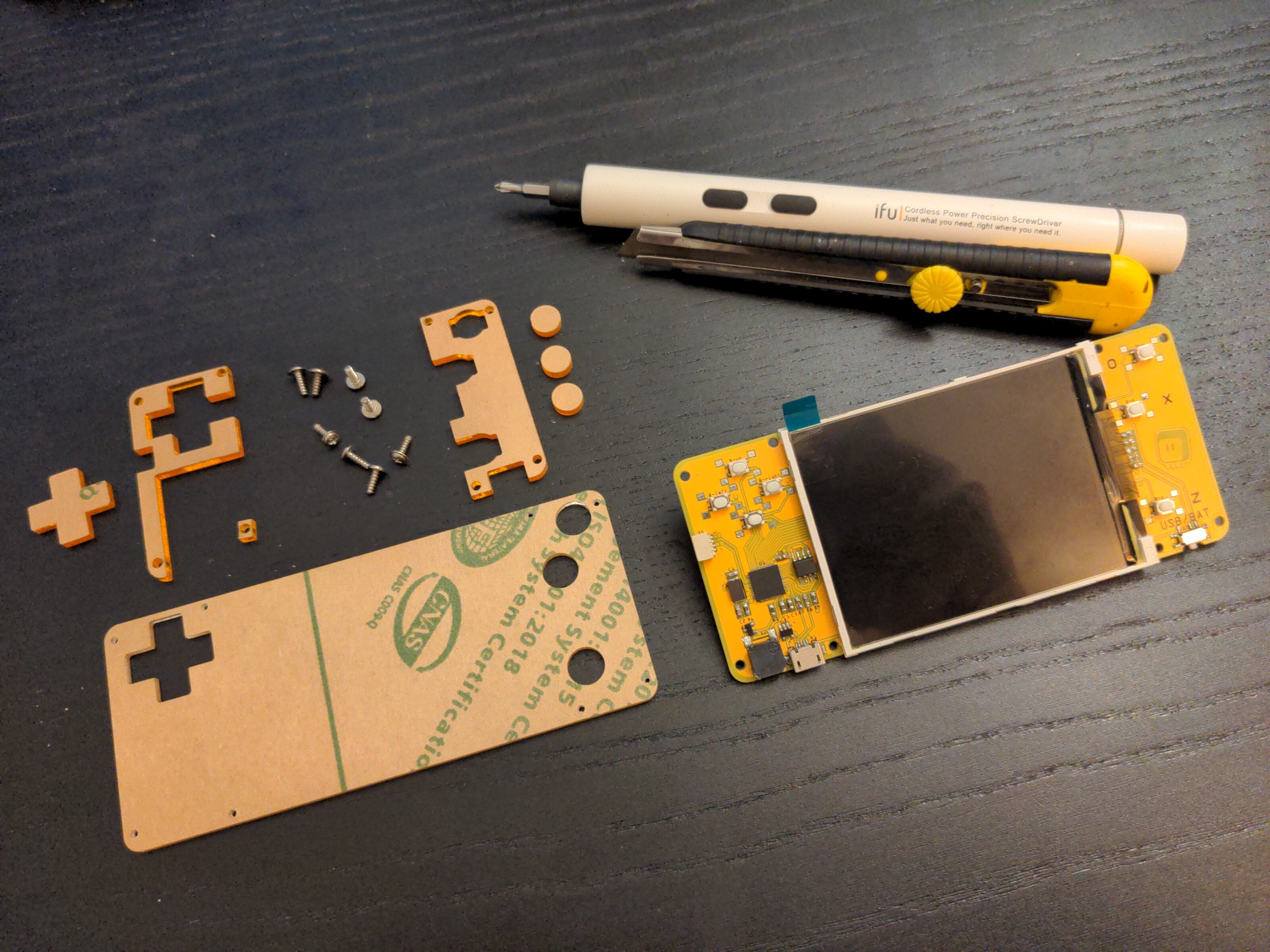
We are going to be working with transparent surfaces, so I strongly recommend doing it in a dust-free environment, with the window closed, away from shedding pets, with freshly washed hands and cleaned tools. Any specks or hair that get inside the device are going to stay there and frustrate you forever.
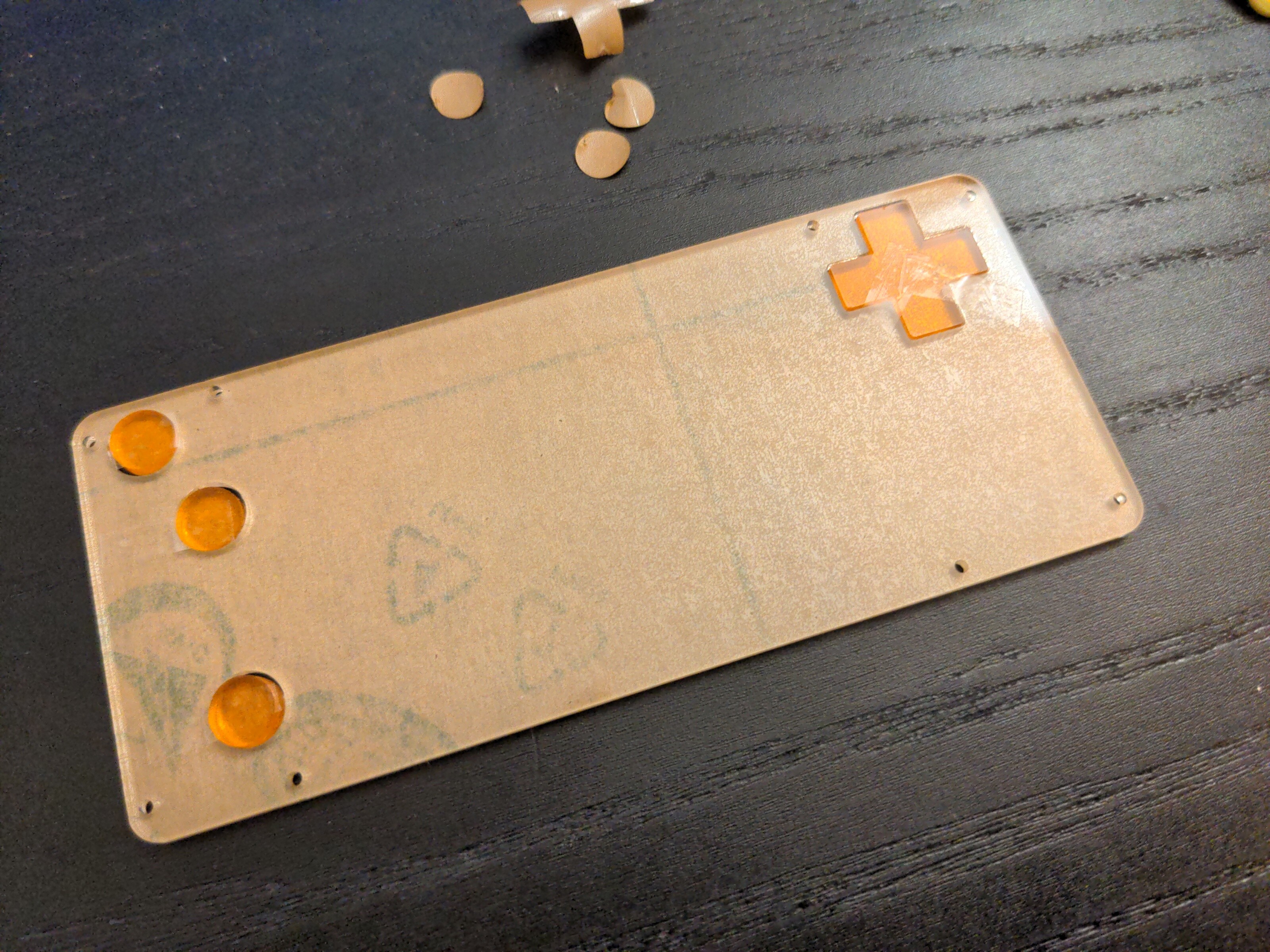
Start by peeling off the paper from the three smaller orange parts that are going to go on each side of the display.
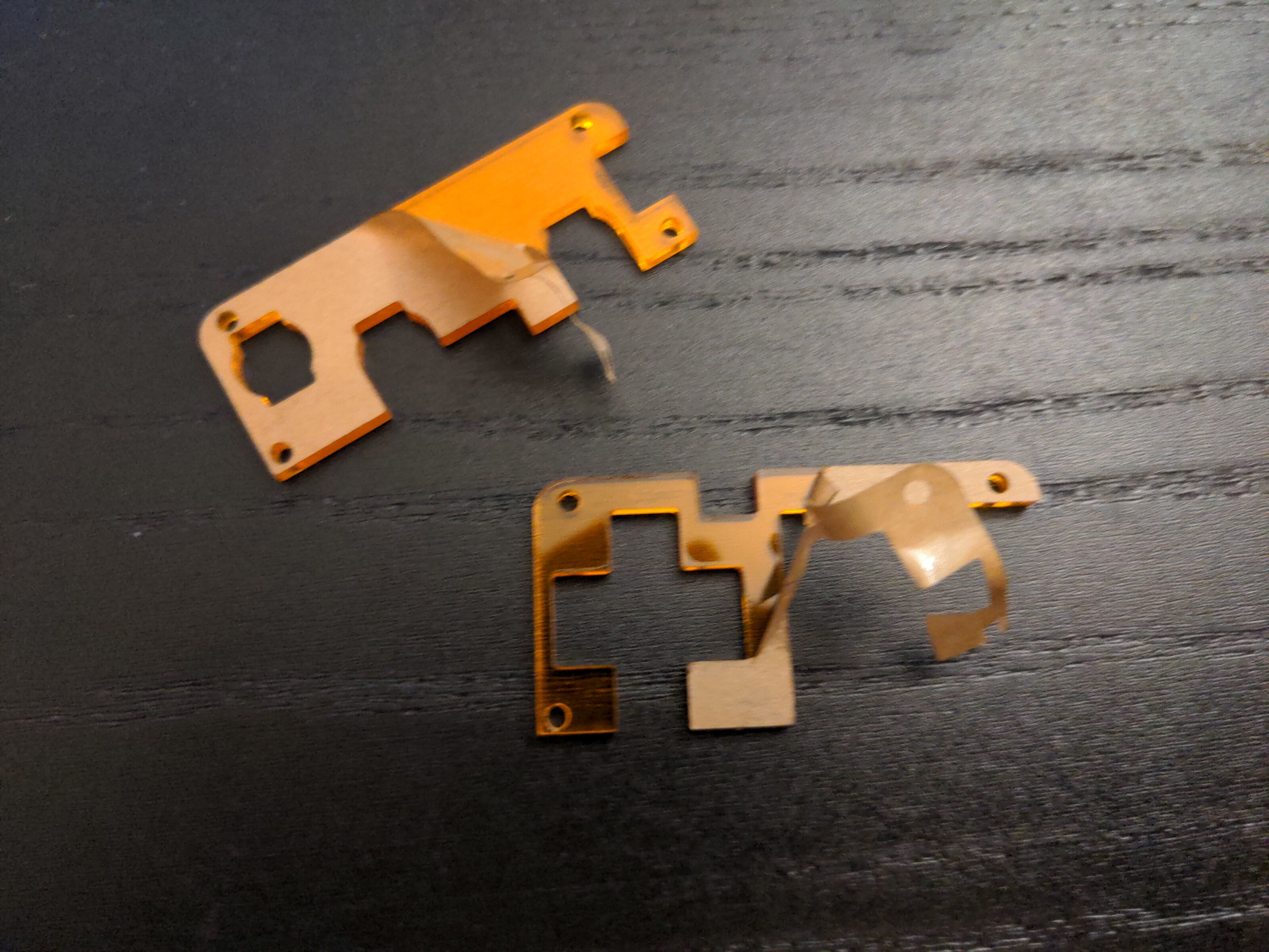
Place them on the PCB. I prefer to actually skip the tiny square part at this point, and add it later, because it’s very easy to drop and lose it.
Next, peel the paper from the back side of the front plate, and from the back sides of the button caps. You can keep the paper on the front side, and only peel it off at the end, when the device is complete.
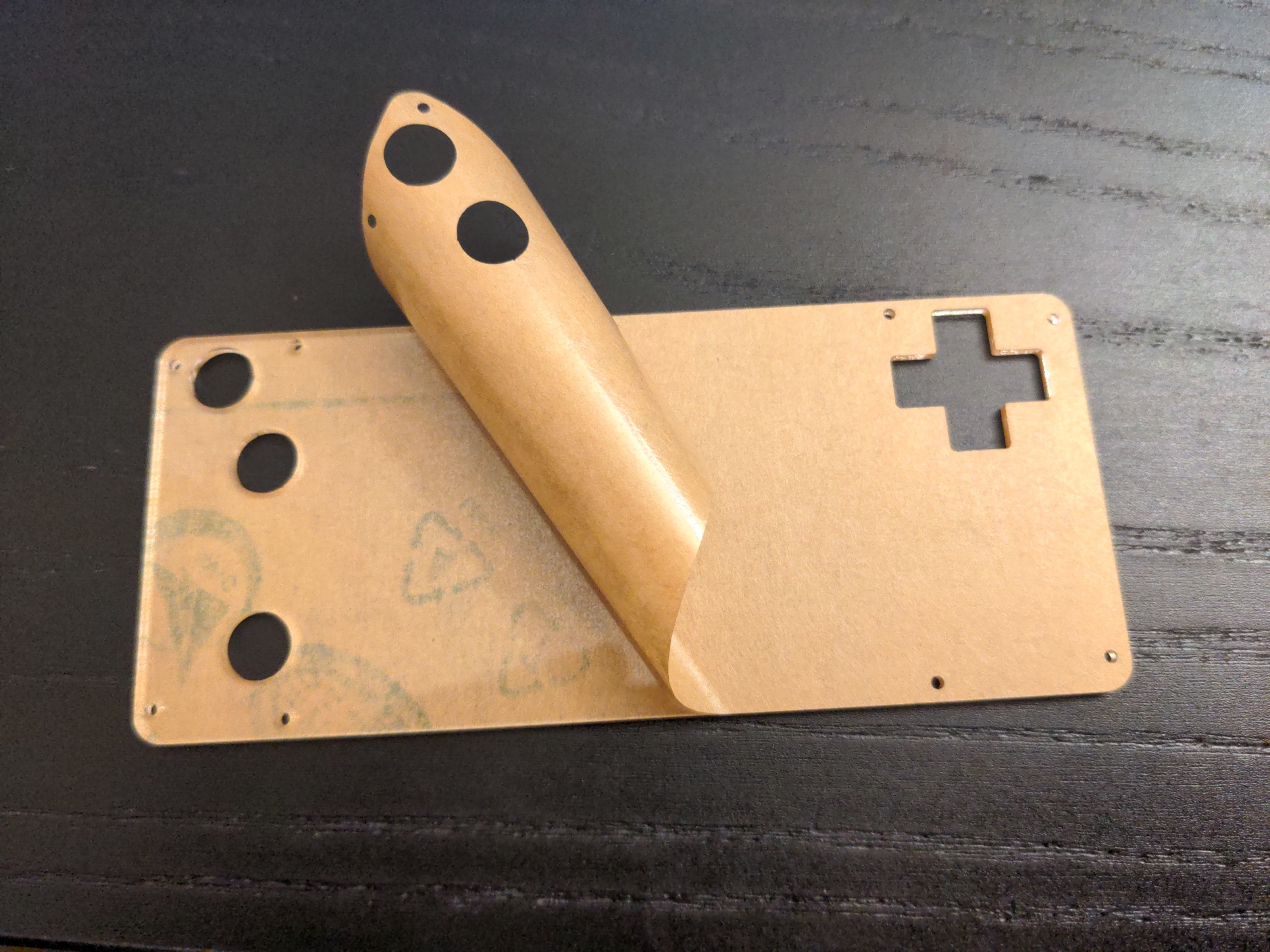
Now place the button caps in the corresponding holes, and secure them in place with small strips of sticky tape. Make sure to only secure them on one side, so they can still move. Be careful when placing the cross button cap, to place it in correct orientation - it’s slightly wider than its height.
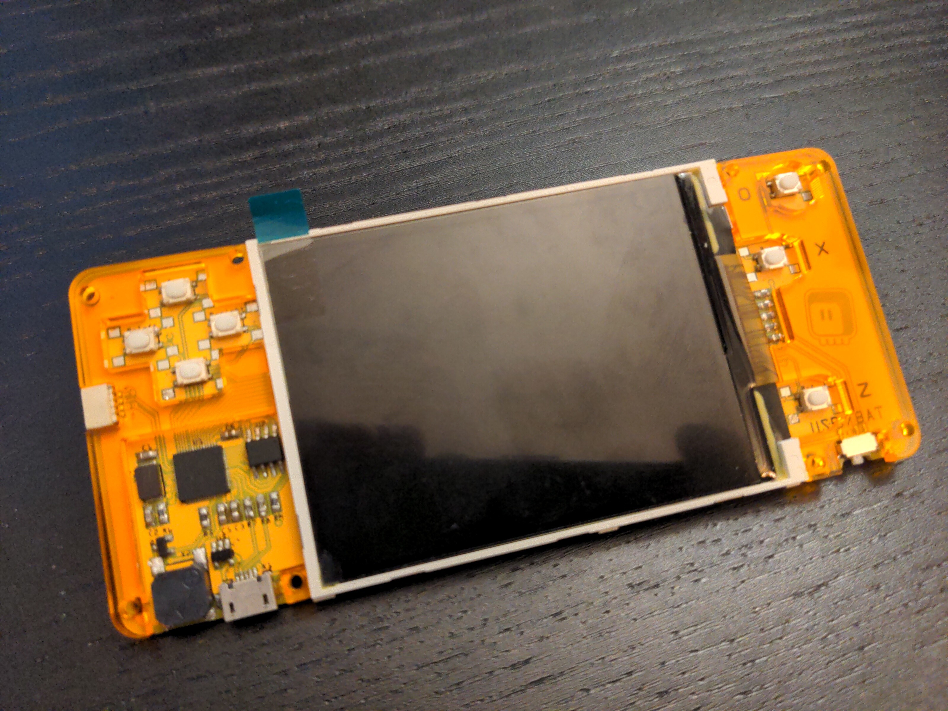
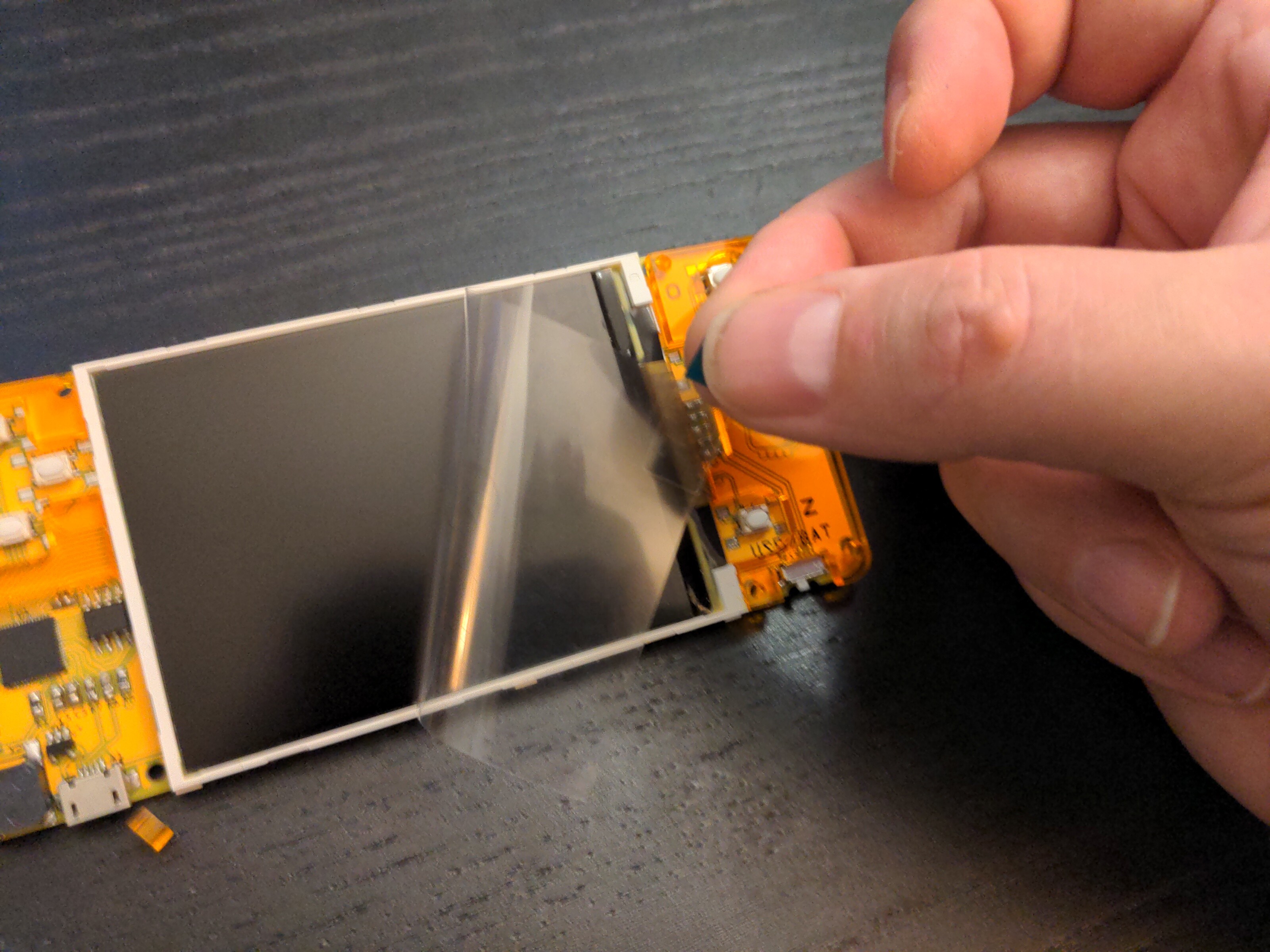
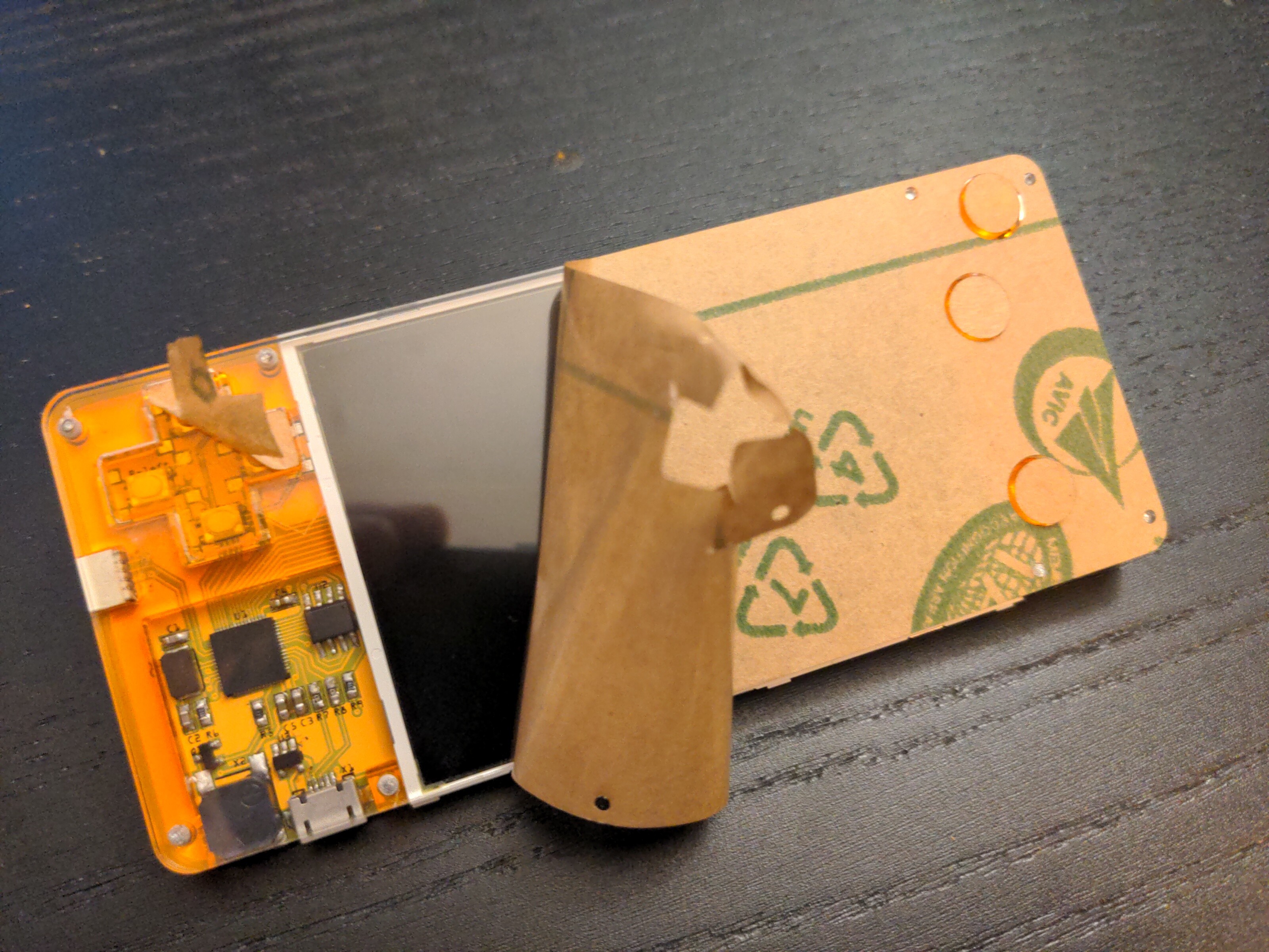
Now peel off the protective film from the display. Be careful not to touch it.
Place the PCB face-down on the front plate, making sure the two orange parts are in place and aligned. Put in the first two screws at the opposite corners.
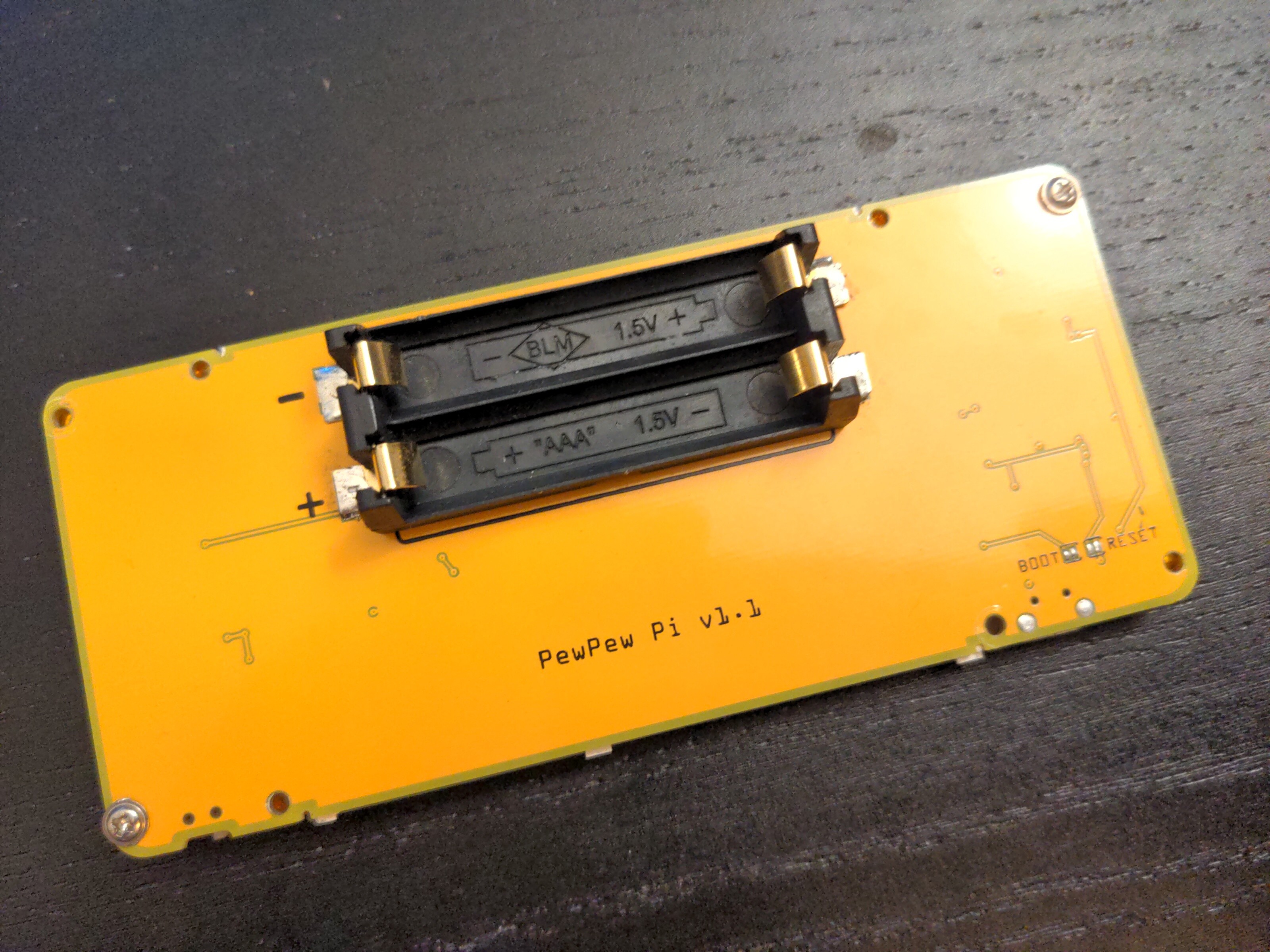
Tighten the screws very gently and slowly. They are self-tapping ans slightly larger than the holes in the front plate, so if you use too much force, the front plate may crack. Next put in place the small square part, and tighten the corresponding screw.
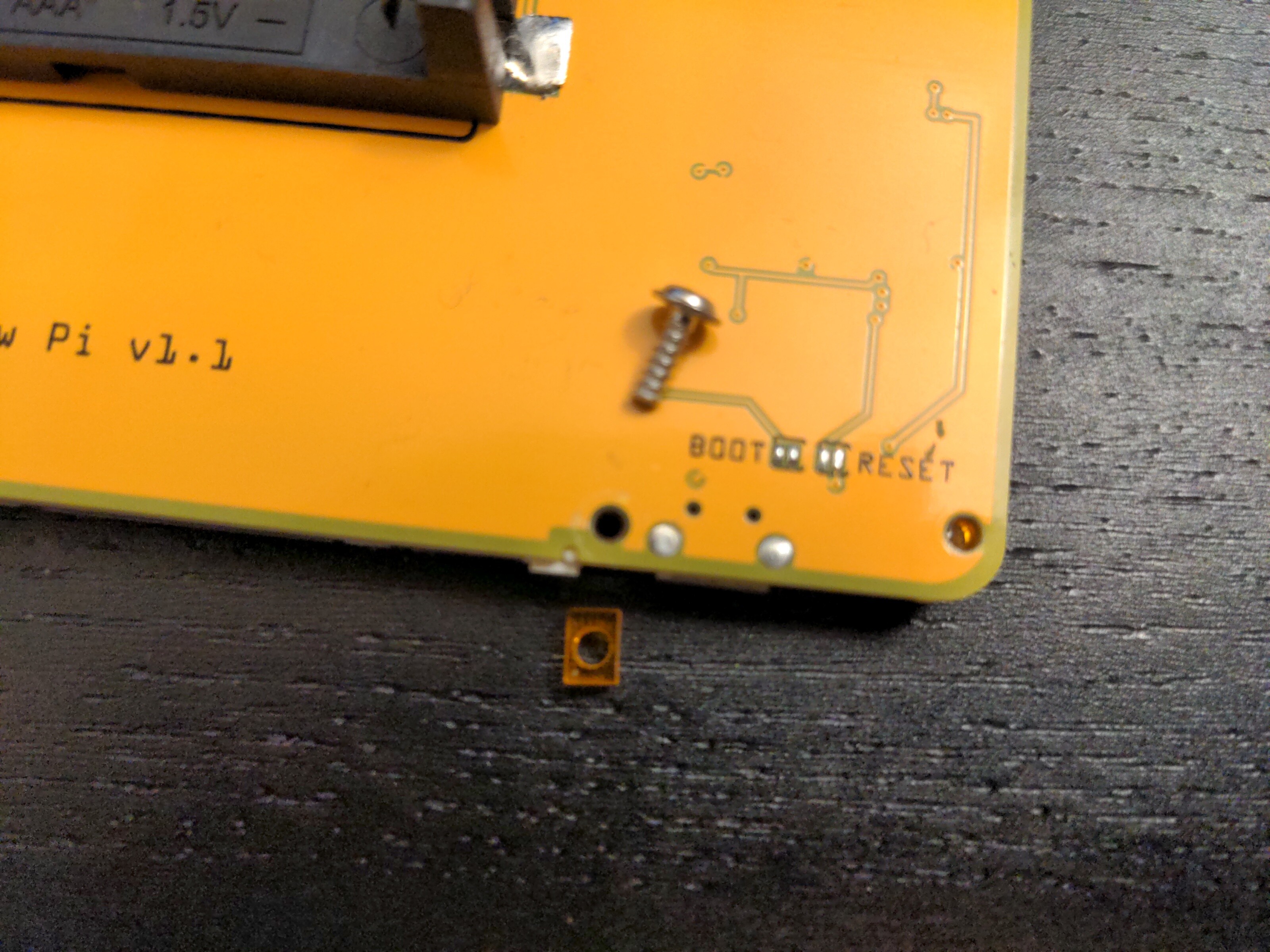
Finish by tightening all the remaining screws. Remember to go slowly and gently, as to not crack the front plate. They don’t have to be very tight, just enough to hold the plate in place.
Finally, flip the device, and remove the paper from the front and the buttons. You are done.
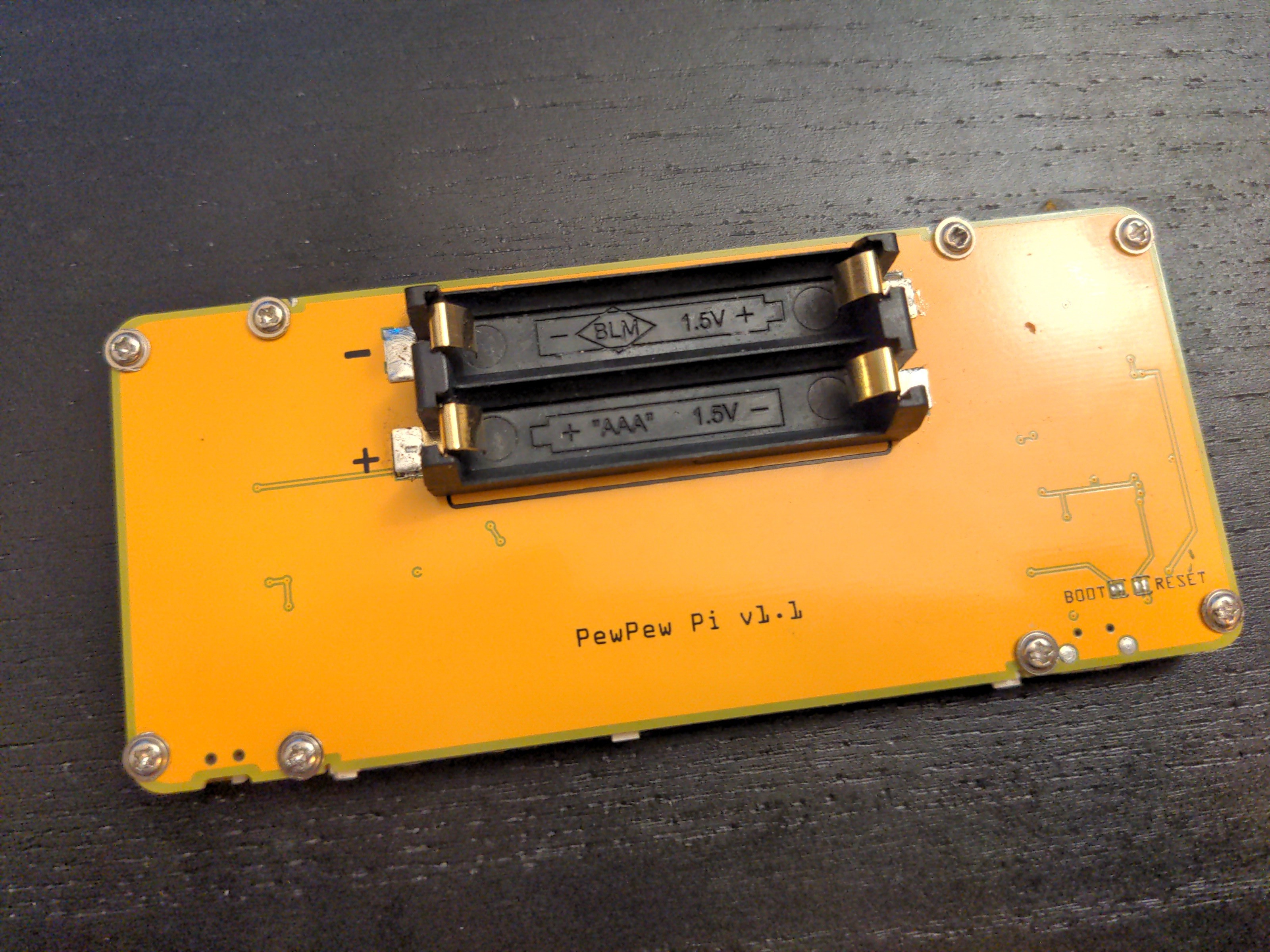
The screws on the photos are prototype screws I had at hand. The final design will use black screws with a smaller and sunken head.