First Hardware
Published on 2022-05-10 in PewPew LCD.
In the mean time, the PCBs that I designed for this arrived from @JLCPCB and I could assemble the first prototype. I can only give you one advice here: don’t design PCBs while sick and with fever. Everything went wrong.
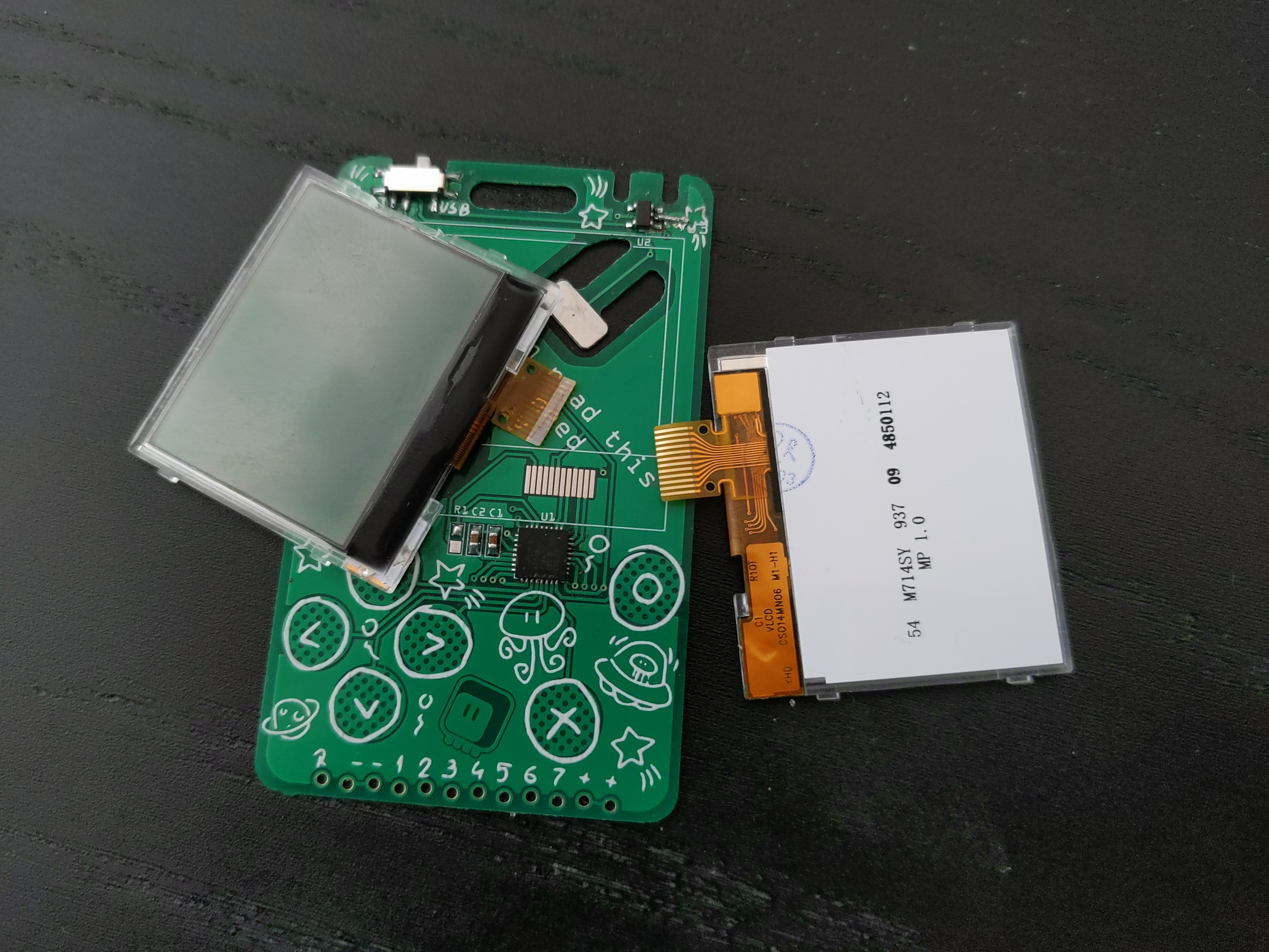
The display footprint had to be custom of course, and I designed it the same way it was done on the breakout I tested with – assuming the flex connector will be folded under the display and soldered there. Well, turns out the really cheap displays I got are a bit cheaper than the one on the breakout, and the flex connector only has metal contact on one side. The wrong side, of course. So I will need to redesign it to move the contacts outside of the display outline.
Fine, so I will need to make a second version for the display connector, but what about the rest of the device? Well, the rest wasn’t very good either. I simply couldn’t get the chip to program. After several hours of struggles, and some smoke coming out of the voltage regulator, I finally realized that I had the USB connector mirrored. It probably happened when I moved it to the other side of the board. Sadly, I burned one of the SAMD21 chips I had, and that’s painful considering we have chip shortage and the next opportunity to buy more will be in a year from now.
At least the physical shape of the PCB is good. The battery connector works great, the expansion header retains a male pin header inserted into it just fine, the touch pads are in the right places and the USB socket fits the plug.