Next Steps
Published on 2022-12-15 in Camera Shield for S2 Mini.
Now that I have it working, what is the next step? Well, right now the shield requires the microcontroller to provide the main clock signal for the camera chip. That means that the camera needs at least one PWM channel to work, and with only 8 channels available on the esp32-s2, and with 8 servo needed on my Fluffbug robot, that doesn’t work very well. But I also have an off-the-shelf camera module that doesn’t even have the main clock pin broken out, because it has an oscillator that takes care of that. Could I add an oscillator to my shield, and make the PWM channel unnecessary? Probably. But how?
Well, let’s search around for schematics of those modules and see if we find any useful hints. The first one I found is already promising:
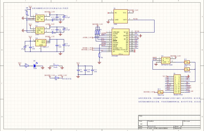
It shows that we only need to connect a single part to the MCLK pin, the one marked as X1, and labeled “24M” underneath. So probably some kind of a 24MHz oscillator. There is some more detailed documentation at https://doc.embedfire.com/mcu/stm32/f407batianhu/std/zh/latest/book/DC MI_OV2640.html#id31 , together with an image:
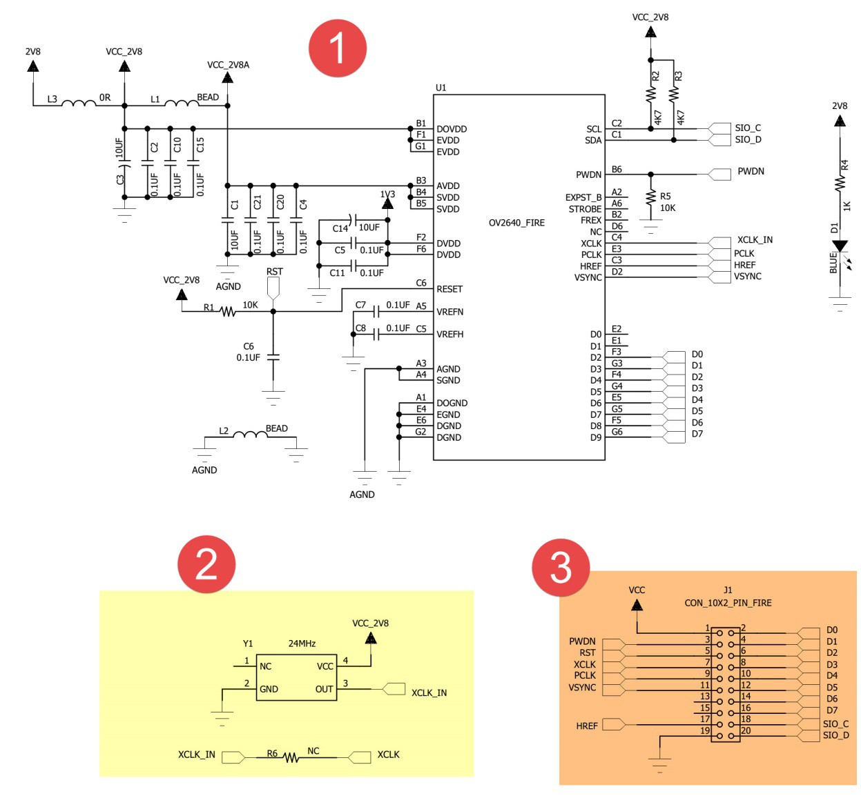
Here the oscillator Y1 is connected through a resistor, but otherwise it seems the same. The text under the image says ” 标号处的是一个24MHz的有源晶振”, which translates to “The label is a 24MHz active crystal oscillator”. So, active crystal oscillator. It’s also powered with the 2.8V, so we need a CMOS one. And I can probably test it without having to make a new PCB, as I don’t much care about accuracy here, just that the clock is provided.
Unfortunately I don’t have any 24MHz active crystals oscillators in my drawer at the very moment, so I will need to order one to see how that works.