Assembly Instructions
Published on 2023-01-30 in Fluffbug.
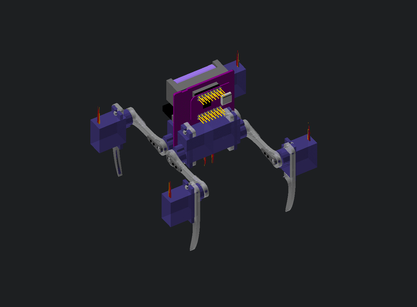
With a workshop quickly approaching, it’s time to spend some effort on the documentation. This time I want to make some IKEA-like step-by- step instructions, so I had to figure out a process for generating the images of the robot parts. Of course I already have an OpenSCAD model of the robot, I just had to update it a little and add some detail:
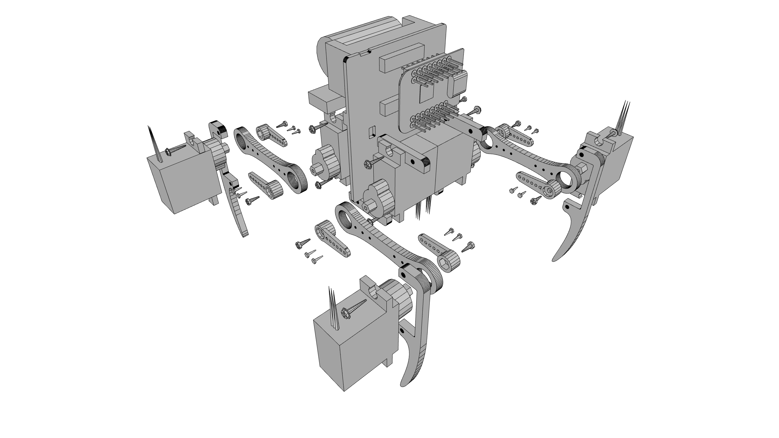
I parametrized the part positions, so that I can easily “explode” the whole thing, showing individual components. But this kind of image is too busy and looks bad when printed on paper in monochrome, so the next step is turning it into a wireframe. After some searching, I found an STL viewer that can do that, so I generated an STL of the robot from OpenSCAD and fed it to the viewer. I got something like this:
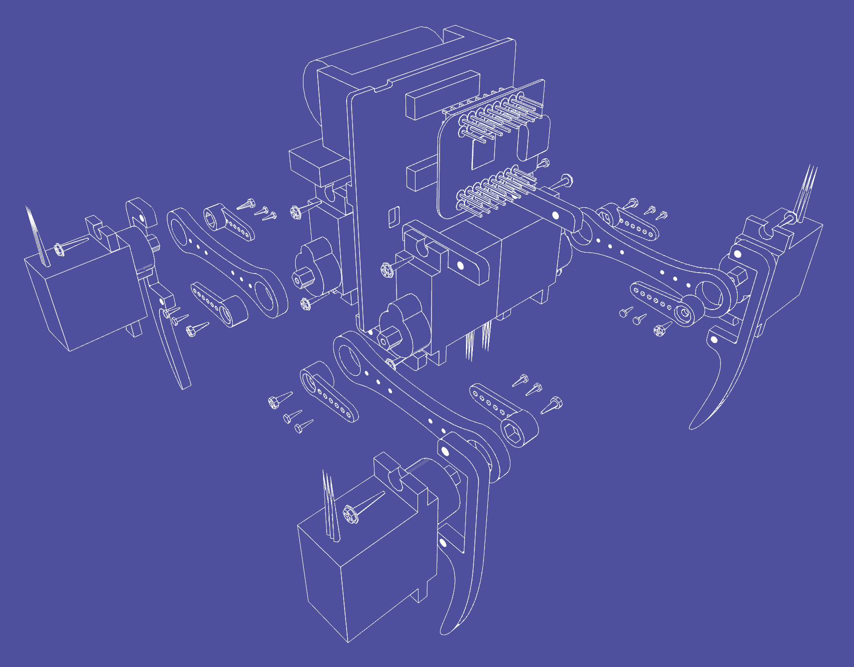
This is much closer to what I want, but there is still a lot of unnecessary detail cluttering the picture and making it hard to see clearly what comes where. So the next step is some manual cleanup in GIMP:
This is exactly what I wanted. Next, I quickly generated scad files for the individual steps of the assembly, and repeated the process to get the illustrations. An (almost) finished guide looks like this:
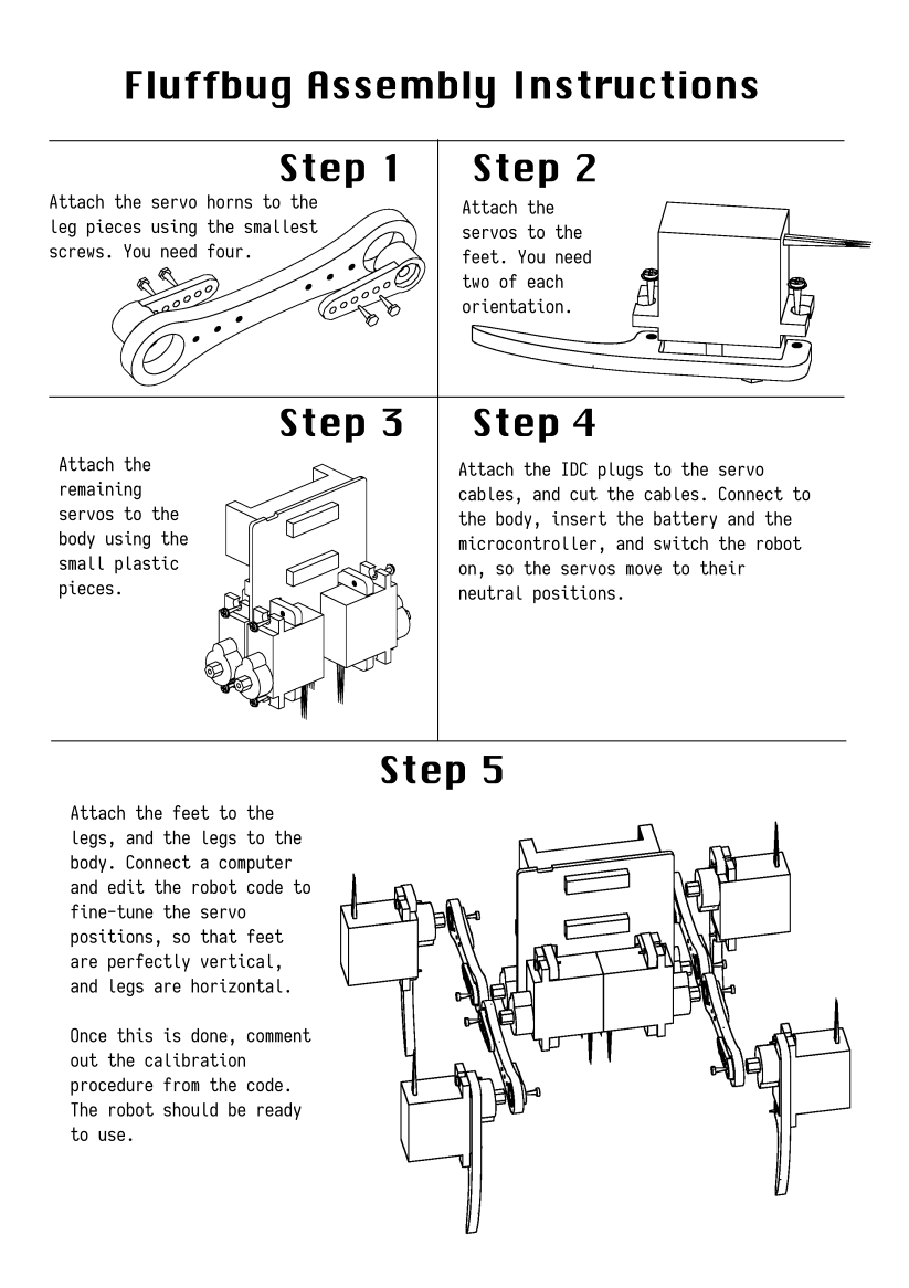
I still need to make the image for step 4, but I’m not sure I want to use OpenSCAD or something else for it. It has to show the orientation and order of the servo cables in the IDC plugs.
In the meantime, I also updated the git repository to include version 8.2 of the PCB and the new leg design.