PCB Physical Fit
Published on 2021-11-02 in Fluffbug.
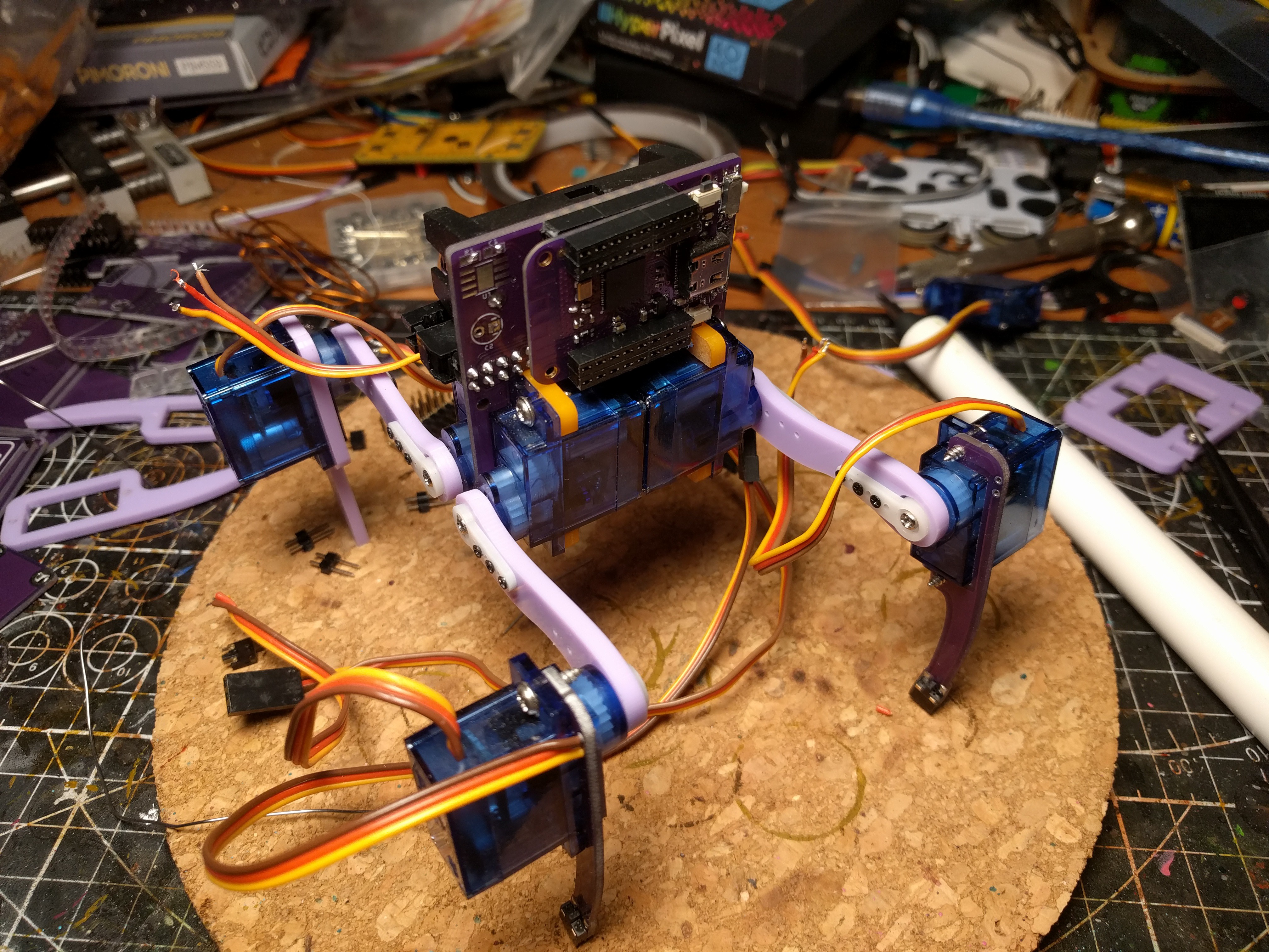
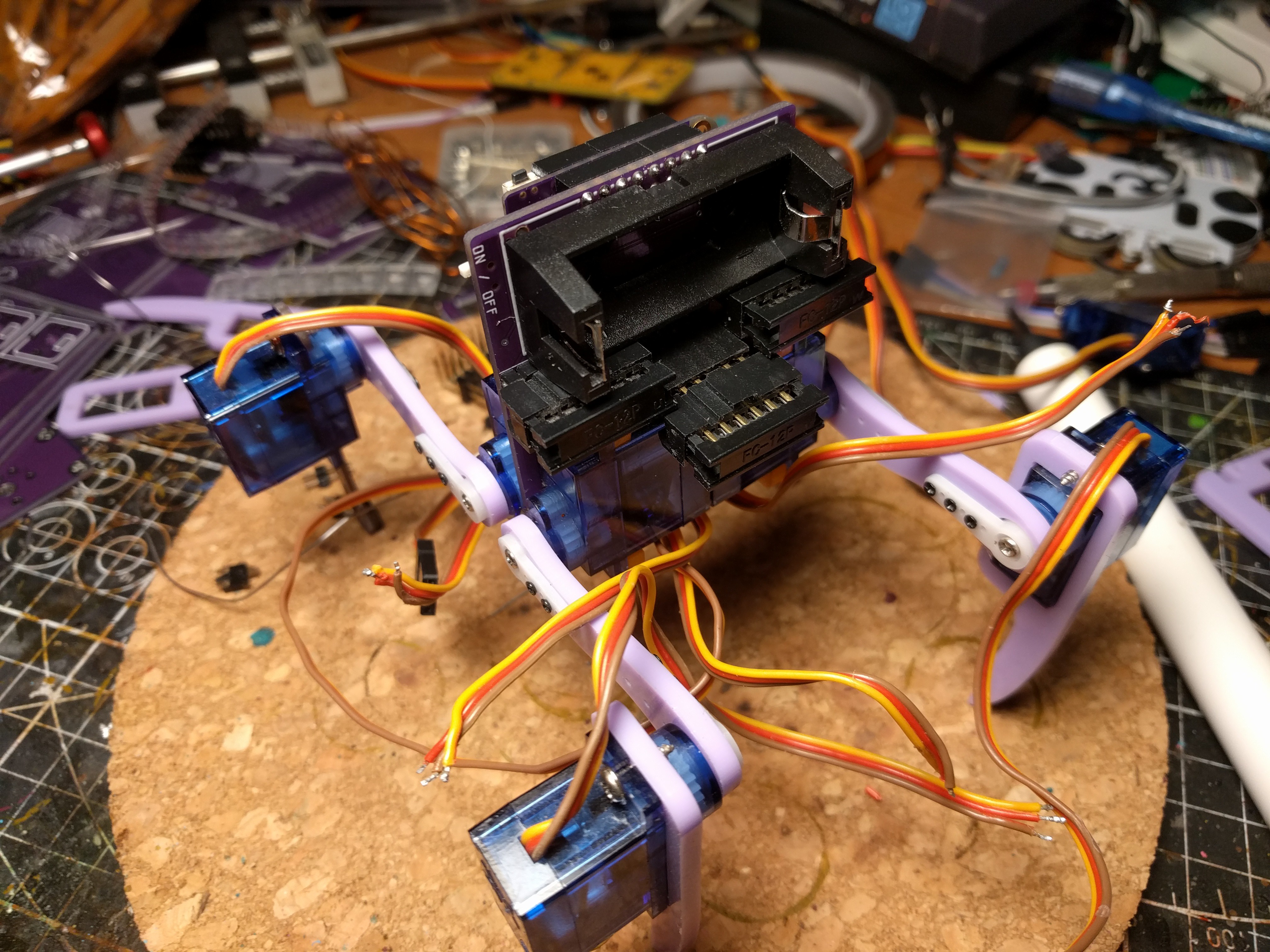
I got the PCBs today, while I still need to solder up all the components and program it, I was already able to test how it comes together physically. In short, it’s workable, but still needs some small adjustments.

The front side of the robot is pretty much fine. The S2 Mini fits in there and sits tight, the USB-C socket has enough clearance, the BOOT button is accessible, the RESET button is a bit hidden, but still accessible with a screwdriver or tweezers. The slots for attaching the servos are the right size and in the right positions.
The legs work, but I would like to move the switch a little bit further down, to give it more travel before the leg hits the ground. I might also make the wire holes a bit bigger, to allow using the servo plugs which will be cut off from the servos.

The back side needs work. I didn’t take into account the thickness of the ribbon cable plugs, and the fact that they are keyed with a nub on top — so there is not enough clearance between them and the battery holder. At the same time, the battery holder is not flush with the top of the PCB, so there is actually room to move it. I had to use stacking pin headers to add distance for the middle plug, otherwise the side plugs and the servos don’t leave enough room for it.
I also want to add some more holes, aligned with the holes in the S2 Mini and in the battery holder. I probably won’t be putting bolts in them, but there is room, so why not have them.
 deshipu.art