Designing Second Prototype
Published on 2021-12-30 in Electronic 6-hole Ocarina.
After several more attempts at fixing the pressure sensor in software somehow, I’ve given up on it, and decided to try a different approach. This time I want to use a microphone placed in the stream of air, and measure the acoustic energy that it picks from the noise of the air rushing by. This should have no problems with a lag or a long recovery time.
To avoid mucking about with analog circuits and amplifiers, I decided to use a PDM microphone — a very simple MEMS device, that takes a clock signal, and gives you back 0/1 pulses that correspond in their frequency to the shape of the waveform — a bit like doing sound output with PWM, only in reverse. Of course CircuitPython already has a audiobusio library that handles it, so it’s really easy to get it working: https://learn.adafruit.com/adafruit-pdm-microphone- breakout/circuitpython
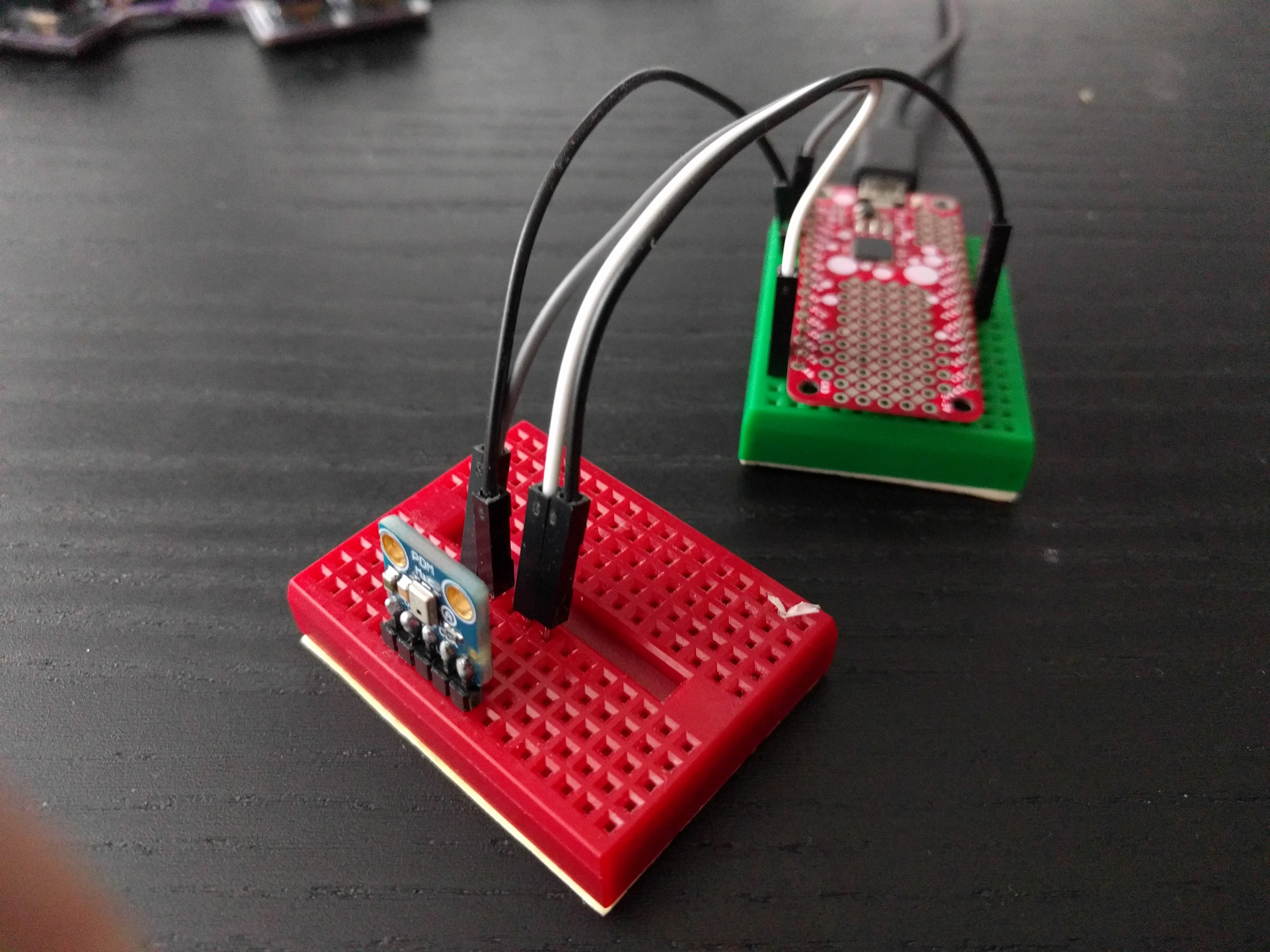
After a test with a module on a breadborad to see if it will work well enough and to determine which pins to use, I went ahead and created a PCB for the new version. I had a moment of doubt when it came to creating the footprint, as the datasheet shows something like this:
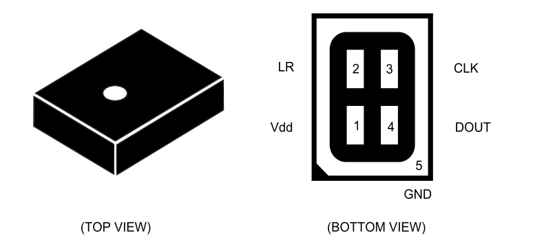
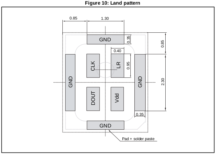
You see, there is no way to route the traces to those pads, unless you use some expensive via-in-pad setup. However, a few pages later they show the recommended footprint, which is a bit more reasonable:
Using this, I created the PCBs and placed the order at JLCPCB. I should be able to continue the experiments in a week or two.
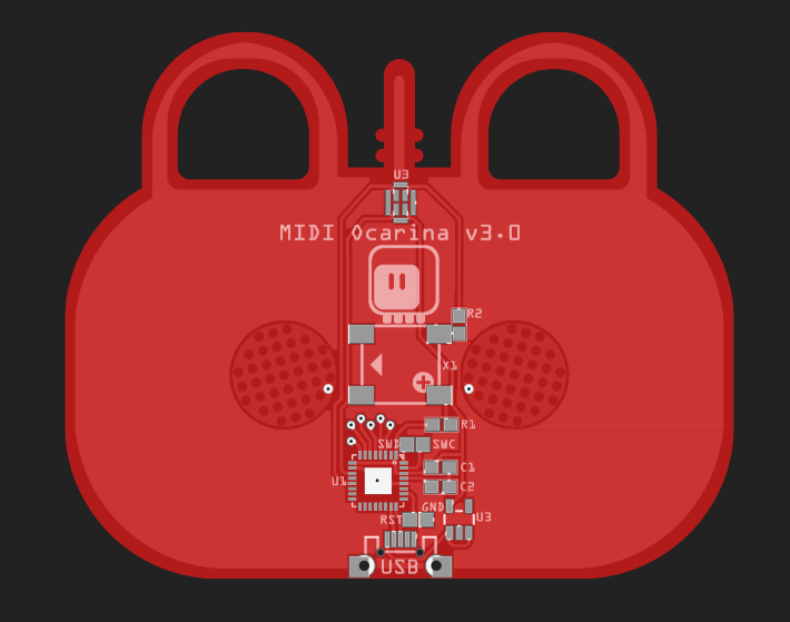
Oh, I also added a footprint for a cheap piezo speaker, I will see if I can PWM the tones.