A Moment of Truth
Published on 2019-12-03 in Flounder Keyboard.
I finally started working on the firmware for this keyboard, starting with writing a board description and compiling CircuitPython for it. Unfortunately that enabled me to find a number of problem with the PCB.
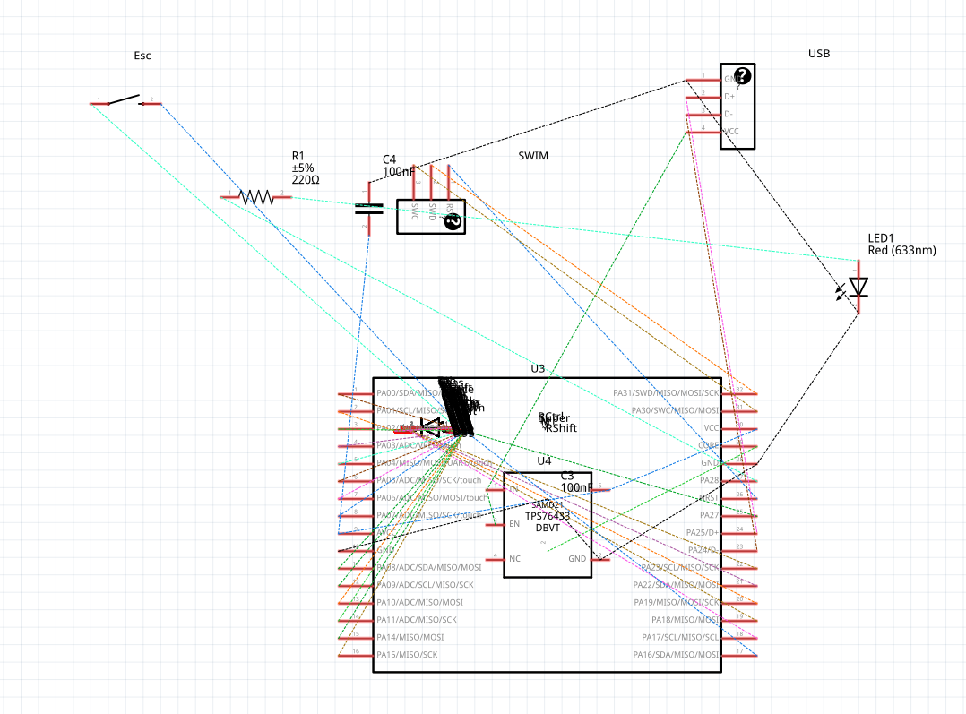
First, I needed to figure out which pins go to which rows and columns, and let me say that the schematic view of Fritzing is not very helpful with that:

It just piled all the switches and diodes on top of each other, and I really don’t have the energy to arrange them all properly. But no problem, we can use the PCB design view, and simply look where each trace goes. If we click the trace, it gets highlighted, together with all things that are connected to it, so that’s not too bad. While doing that, I noticed a curious thing:

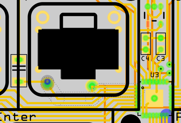
Apparently I wasted one of the pins, by connecting it directly to the backslash button, before the diode. This isn’t a problem, since there are still enough pins (just barely), and there is another pin properly connected to the whole row after that diode, but it shows what my mental state was when I was designing it.
With the CircuitPython compiled and flashed, the next step is to try the KMK firmware. Unfortunately, it doesn’t even fit on the 45KB flash disk my tiny SAMD21 has — not even compiled to byte-code. So I started trimming. Removed all the tap-dancing and leader-key code, all the debugging prints, all the RGB LED handling, Unicode keys, and so on. Finally I got it to a size that just barely fits, together with a layout definition. And of course I get MemoryError. Fine, I will write my own keyboard firmware in CircuitPython. With blackjack. And hookers.
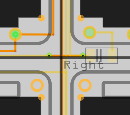
The first step was to wite the matrix scanning code, of course. That went fast, but I noticed a weid quirk: whenever I pressed a key from row 3, the key from row 4 would also get pressed. And the other way around, pressing a key from row 4 would also press a key from row 3. Seems like there is a short between the two rows. I couldn’t see any obvious problems, so I just touched up the QFN package a bit, to make sure there is no short underneath, but no dice. Took out my trusty ohmmeter, and noticed that the resistance is pretty much that of a solid trace — that doesn’t look like some accidental short somewhere. To make sure, I took an unpopulated board, and checked there — sure enough, there is a short as well. That made me look closer at the traces, and sure enough:

The row 4 is dipping under the column traces here, but there is also a hard-to-see trace for the row 3 going right through it on the underside of the PCB. It’s hard to see, because I rooted it along a silkscreen line, genius. Cutting that trace on both sides and connecting the two vias with a piece of wire solved this problem.
Next, Caps Lock and the A key seem to be the same key — no matter which one I press, I get the same matrix position. Looking closer, yes, of course I connected both to the same row and column. Fortunately, soldering the diode for Caps Lock up-side down, and then adding a wire leading to Left Ctrl on row 5 fixed the problem. It moved the key to row 5, where there is a free spot. Maybe the layout definition will look a bit confusing, but who cares.
Finally, five of the keys had the diodes soldered only on one side — re-touching them with the iron fixed it.
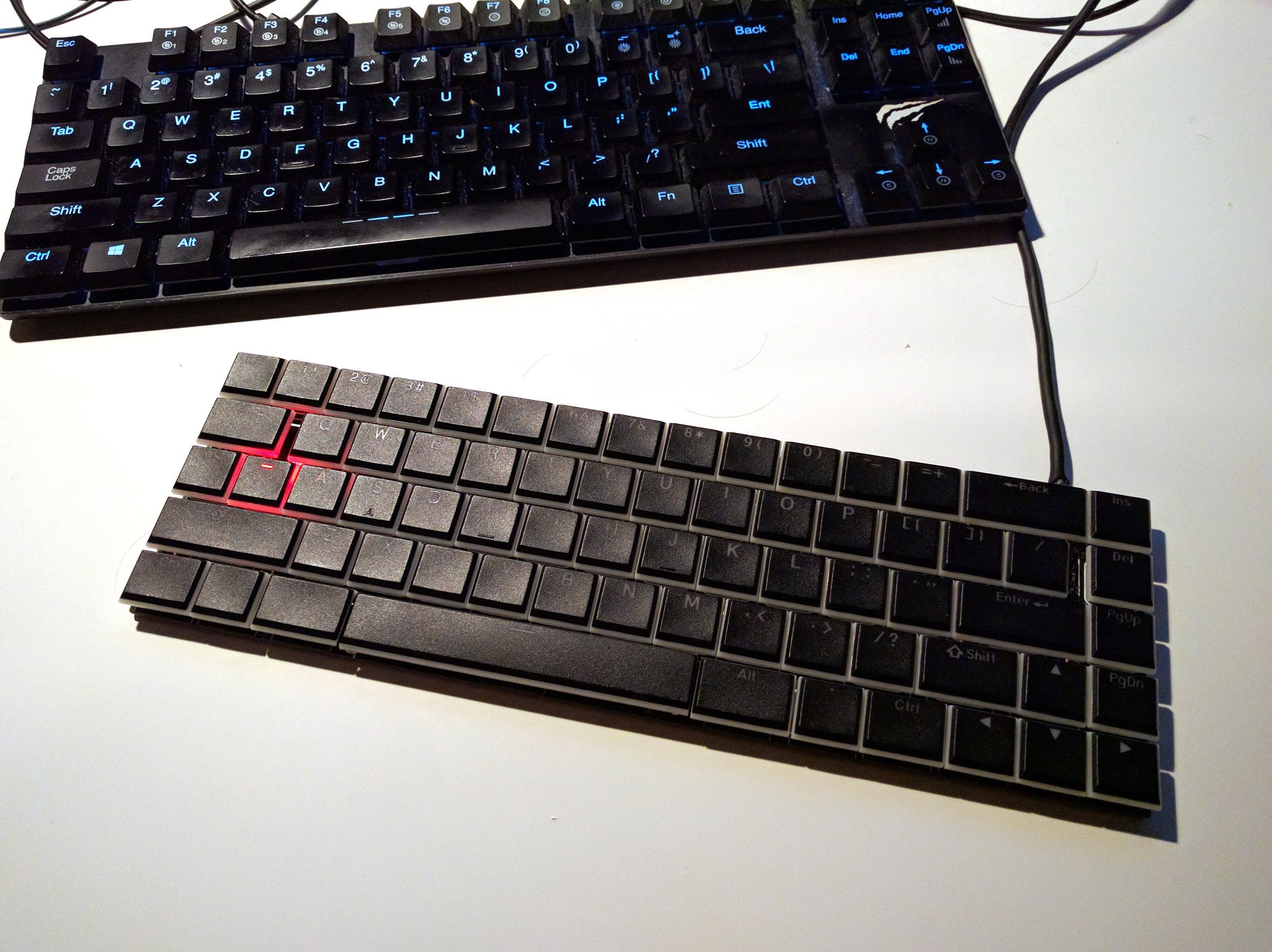
It all works now mechanically, even the Caps Lock led:

Next time, more about the firmware.
 deshipu.art