Here We Go Again
Published on 2018-08-01 in PewPew Standalone.
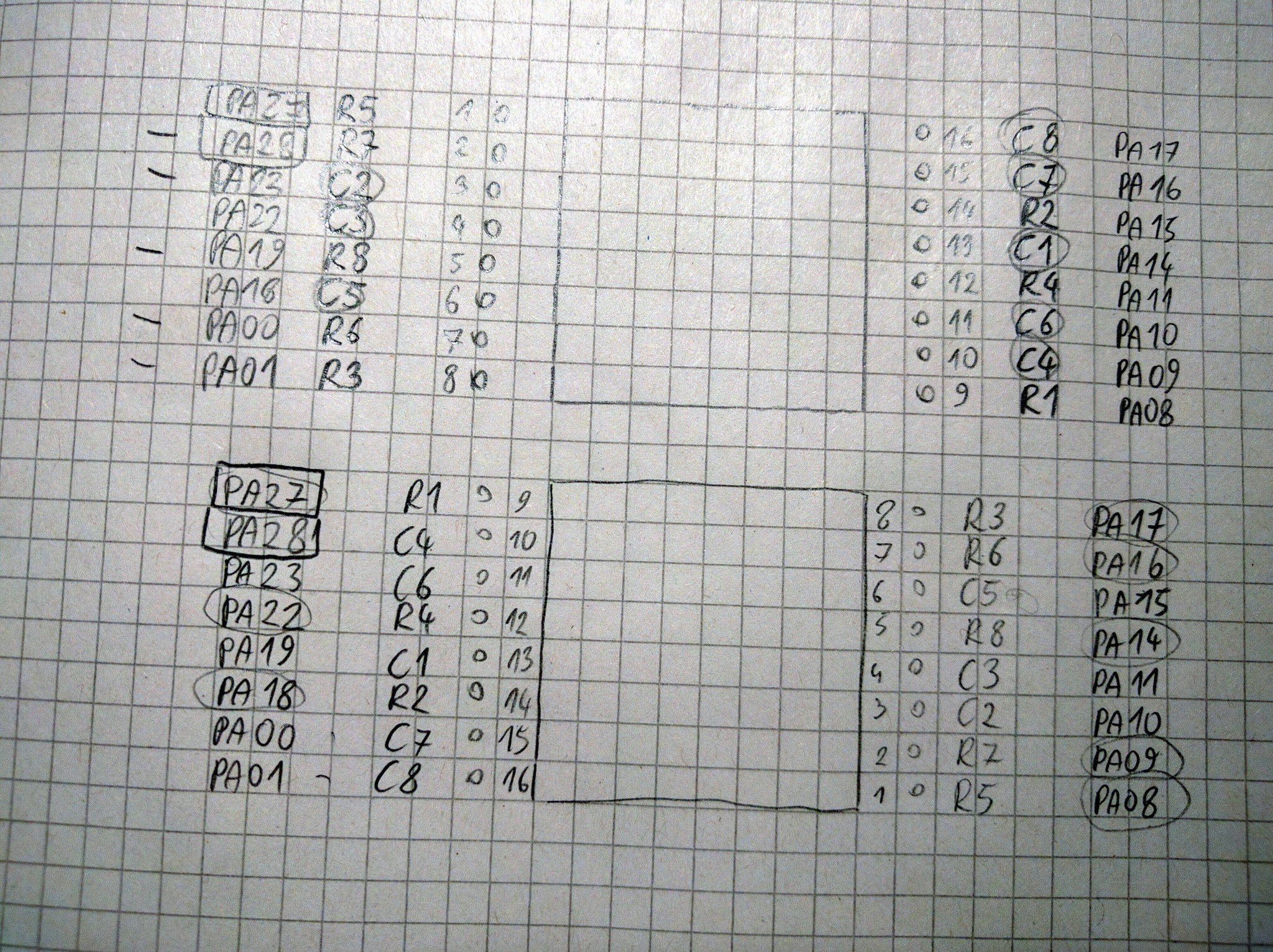
In the previous log I mentioned that I need a better solution to dim the LEDs — the system tick interrupt doesn’t fire fast enough for me to have a good enough refresh rate to do it in software. I decided that I will do this by using PWM on the row pins — I can make the PWM frequency high enough that it won’t interfere with the column scanning, and then I have a really nice 16-bit range of shades. However, there is a small problem with this: two of the row pins are connected to GPIO ports that don’t support PWM. The culprits are R5 (PA27) and R7 (PA28). I checked if I could perhaps solder the matrix up-side-down to make those pins be connected to columns instead, but no, it works for PA28, but PA27 is then connected to R1.

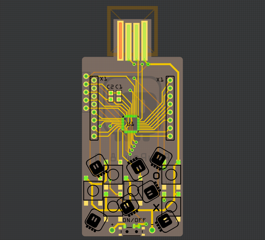
So I have no choice: a new PCB design is needed. To be honest, that was coming anyways, as the spacing of pads in the USB plug wasn’t perfect, and I wasn’t proud of the right-angle traces. So I removed the connections, rotated the microcontroller by 90°, and re-connected everything, paying attention to use PWM-capable pins for the rows. I think it came out much cleaner this time:

The “forbidden” pins, PA02, PA03, PA27 and PA28 are all used for buttons now. I will mull over the design a little bit more, and order it from OSHPark this time.
 deshipu.art