Servo Breakout for WeMos D1 Mini
Connect servos to your ESP8266 dev board.
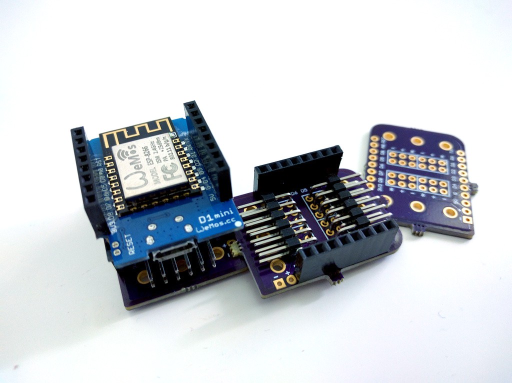
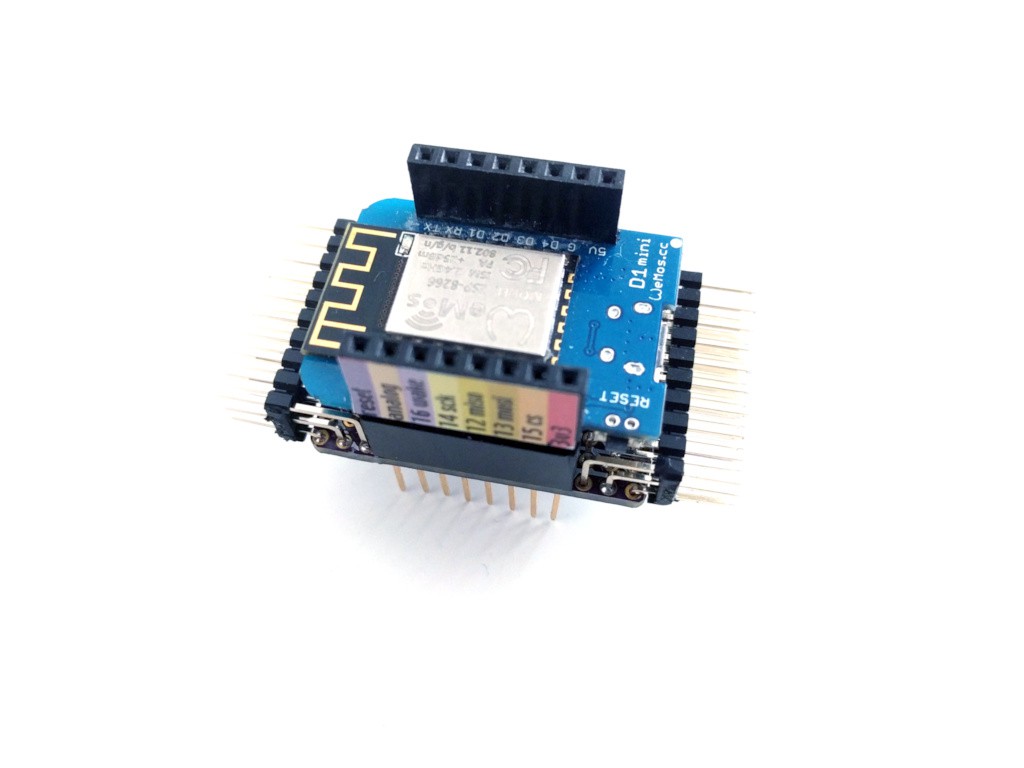
I thought I will try to make some shields for the WeMos D1 Mini, because it’s one of my favorite ESP8266 boards. There is already an official motor controller shield (though I can’t get it to work reliably), so I decided I will make some servo shields.
Logs
2020-12-19 - Maybe SX1509?
2020-08-20 - New Seller
2019-02-21 - New Batch
2017-12-04 - Fabrication and Version 2.0
2017-08-01 - Faster Assembly
2017-04-04 - Assembling and Testing
2017-03-24 - Version 1.0 of the 16-channel Shield on Sale
2017-03-01 - Usage Examples
2017-02-25 - Selling Prototypes on Tindie
2017-02-23 - PCA9685
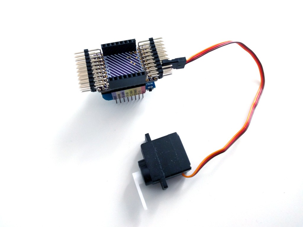
2017-01-20 - 20ch Servo Shield Assembled
2017-01-20 - 20ch Firmware Improvements
2016-12-19 - Firmware for the 20-servo Shield
2016-12-18 - Smaller PWM Code
2016-12-13 - Firmware in Plain C
2016-11-30 - Pimped 20-channel PCB
2016-11-30 - One-sided PCB
2016-11-30 - 20-channel Servo Shield
2016-11-11 - Another Short
2016-10-09 - Released
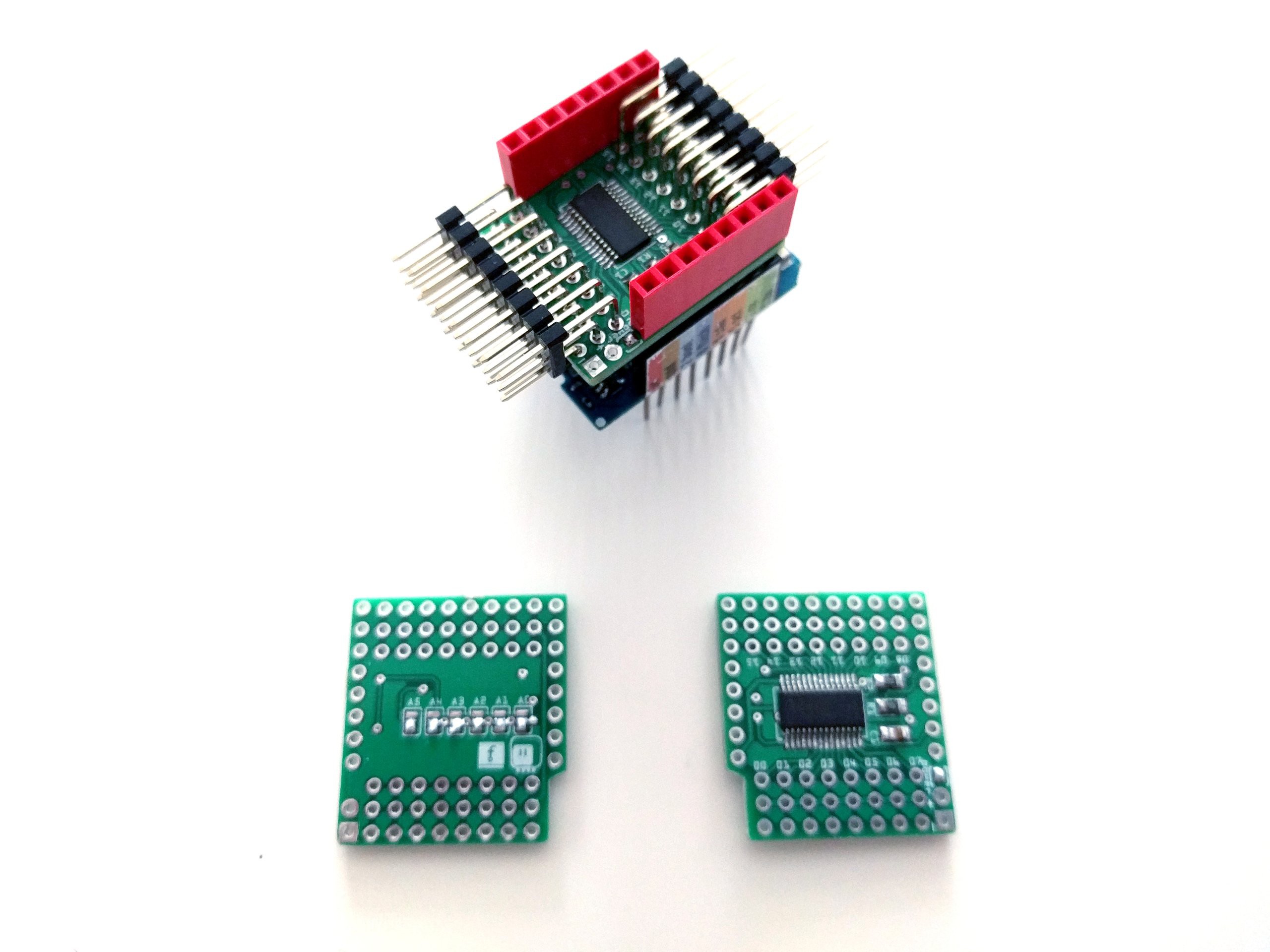
2016-09-15 - Shield Anatomy
2016-09-14 - Dumb 8-channel Servo Breakout
2016-09-14 - 18-channel Servo Shield
Links
Instructions
Get the PCB from https://oshpark.com/shared_projects/QrjTnDg1
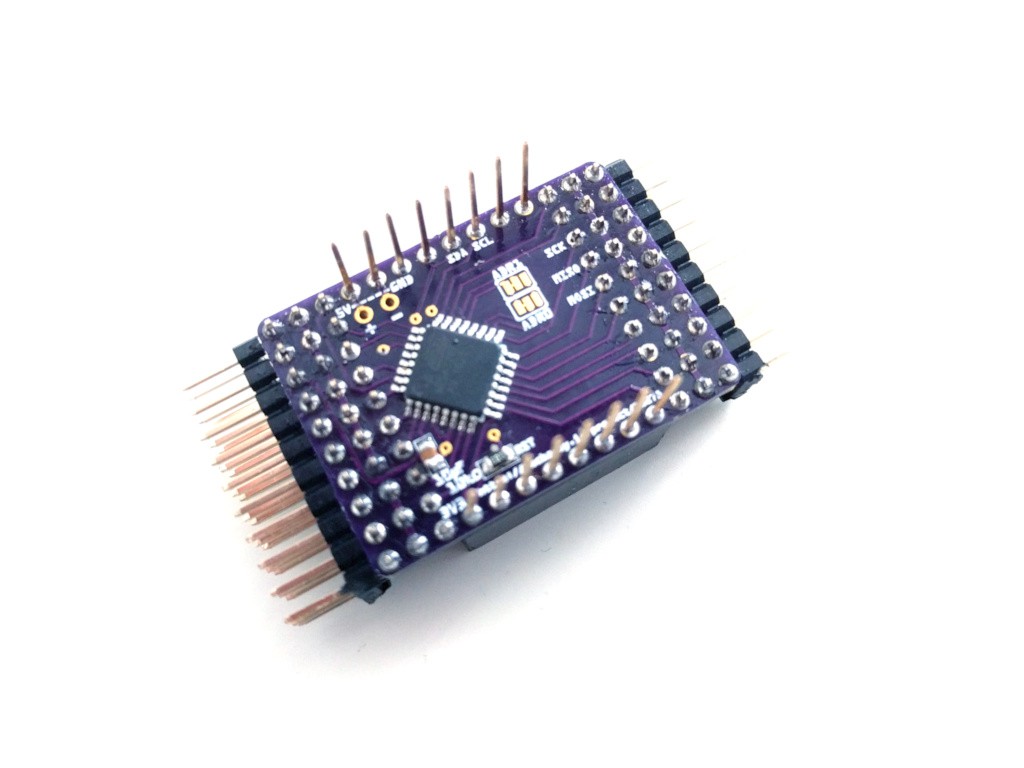
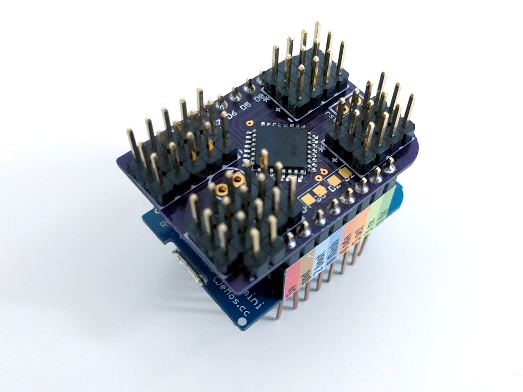
Populate the PCB – solder the ATmega328p, the reset resistor (10kΩ), the I2C pullup resistors (10kΩ, optional), capacitor (10-1000µF, optional). Solder the pin headers for the servos and power, and an extra pin or wire for the reset.

Connect your ISP programmer to the 3v3, GND, MISO, MOSI, SCK and Reset pins as follows:
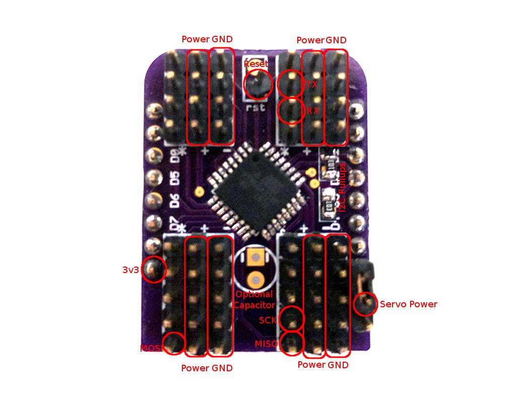
If you are making the 2ch version, the pin names are printed on the PCB. Get the source code from https://bitbucket.org/thesheep/d1mini-18ch-servo/src for the 18-channel version or https://bitbucket.org/thesheep/d1-mini-20ch-servo/src for the 20-channel version. To flash the 18-channel version, use Arduino IDE. To flash the 20-channel version, run “make flash” in the firmware directory.
After flashing, set the fuses with:
avrdude -c usbasp -p m328p -U lfuse:w:0xE2:m -U hfuse:w:0xDF:m
Your shield is ready to be used!