Controller PCB
Published on 2016-04-06 in Pony Bot.
While I wait to cut the new legs, I also prepared a new PCB for the controller. I plan to use an ESP-12 module with Micropython on it to control the eight servos, but I can’t use the same board I had in project-8521 , because Micropython allows PWM on different pins. So I went and made a quick breakout board again, this time with plenty pull-up and pull- down resistors, so that I can also use those pins that normally select the boot mode:
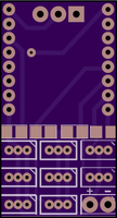
As you can probably guess from the color, the PCB is ordered from OSHPark – I prefer it for the boards smaller than 5×5cm, even though the shipping from US takes ages. The connections are nothing special – all the servos are connected to all the PWM-capable pins, serial and ground are available at the top, and power is at the bottom. I used holes instead of pads for attaching the ESP-12 module, because that is easier to solder. The antenna will stick out at the top. The four SMD resistors provide pull-ups for CH_EN, GPIO0 and GPIO2, and a pull-down for GPIO15. I will need to pick the values of the resistors such that they work well with the servos connected to those pins (well, except for CH_PD). I have the ADC and the serial pins available, so I will probably use them for some sensors – not sure what exactly yet.